Capturing Continuous Data Streams
This tutorial shows how to use Analyzer2Go to capture data continuously. This mode is used to capture large portions of data non-stop and then analyze and annotate them. Before you begin, follow the basic Analyzer2Go tutorial to get the basics running.
In this tutorial we will use one STM32F4Discovery board to generate signals showing the timings of the interrupt handlers and another STM32F4Discovery board controlled by Analyzer2Go will be used to capture those signals.
Compile and download the following program into the generator board:
static TIM_HandleTypeDef s_Timer = {
    .Instance = TIM4
};

void SysTick_Handler(void)
{
    HAL_GPIO_WritePin(GPIOD, GPIO_PIN_14, GPIO_PIN_SET);
    HAL_IncTick();
    HAL_SYSTICK_IRQHandler();
    HAL_GPIO_WritePin(GPIOD, GPIO_PIN_14, GPIO_PIN_RESET);
}

extern "C" void TIM4_IRQHandler()
{
    HAL_GPIO_WritePin(GPIOD, GPIO_PIN_13, GPIO_PIN_SET);
    HAL_TIM_IRQHandler(&s_Timer);
    HAL_GPIO_WritePin(GPIOD, GPIO_PIN_13, GPIO_PIN_RESET);
}

void DemonstrateInterrupts()
{
    int prescaler = 16;
    int period = 999;

    __TIM4_CLK_ENABLE();
    s_Timer.Init.Prescaler = prescaler - 1;
    s_Timer.Init.CounterMode = TIM_COUNTERMODE_UP;
    s_Timer.Init.Period = period - 1;
    s_Timer.Init.ClockDivision = TIM_CLOCKDIVISION_DIV1;
    s_Timer.Init.RepetitionCounter = 0;

    if (HAL_TIM_Base_Init(&s_Timer) != HAL_OK)
        asm("bkpt 255");
    if (HAL_TIM_Base_Start_IT(&s_Timer) != HAL_OK)
        asm("bkpt 255");
    __HAL_TIM_ENABLE_IT(&s_Timer, TIM_IT_UPDATE);
    NVIC_EnableIRQ(TIM4_IRQn);

    __GPIOD_CLK_ENABLE();
    GPIO_InitTypeDef GPIO_InitStructure;

    GPIO_InitStructure.Pin = GPIO_PIN_12 | GPIO_PIN_13 | GPIO_PIN_14;

    GPIO_InitStructure.Mode = GPIO_MODE_OUTPUT_PP;
    GPIO_InitStructure.Speed = GPIO_SPEED_HIGH;
    GPIO_InitStructure.Pull = GPIO_NOPULL;
    GPIO_InitStructure.Alternate = GPIO_AF2_TIM4;
    HAL_GPIO_Init(GPIOD, &GPIO_InitStructure);
}
As the continuous mode uses lower sampling frequencies than the regular frame-by-frame mode, ensure that the board generating signals is running at a reduced frequency (the default frequency after reset is usually slow enough). If you are using a different board, specify the timer period and prescaler that makes the timer frequency very close to the SysTick period.
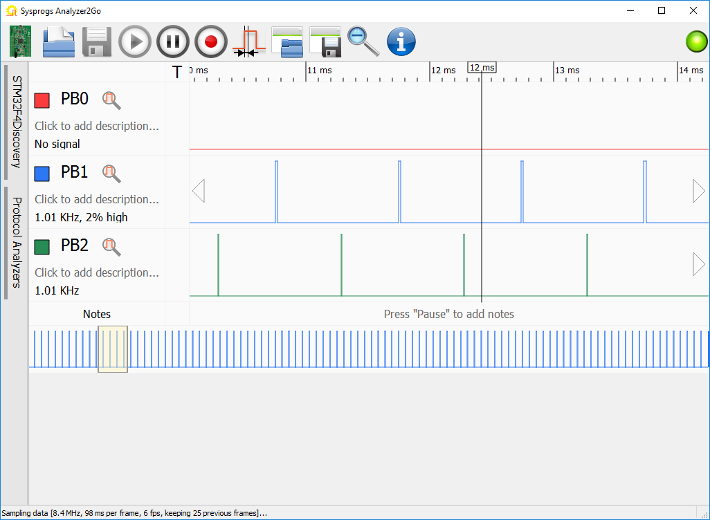
- Start Analyzer2Go and connect the input pins of the board used as a logic analyzer to the PB13 and PB14 channels that will show the interrupt timings on the first board. You will see that the timer interrupt and the SysTick interrupt occur at roughly the same frequency:
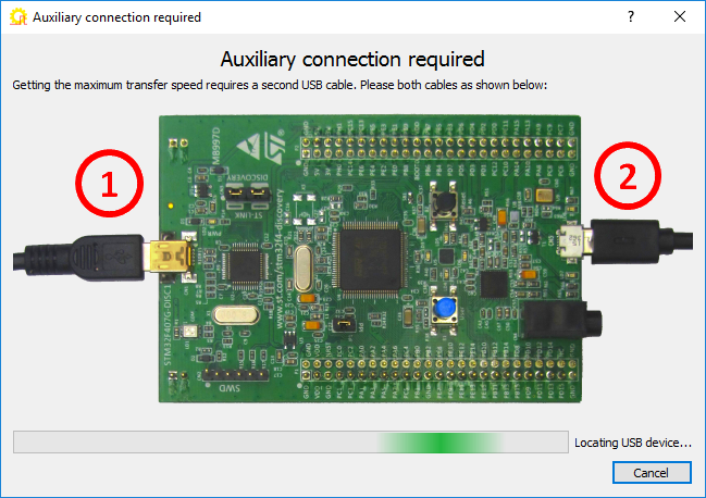
- We will use Analyzer2Go to see what happens when both interrupts coincide. As that event happens relatively rarely, the chance that it will fit into a random frame is very low, so we will use the continuous capture mode to capture several seconds of measurements non-stop. Click the “Record” button. Analyzer2Go will ask you to connect the second USB connector to get the maximum transfer speed:
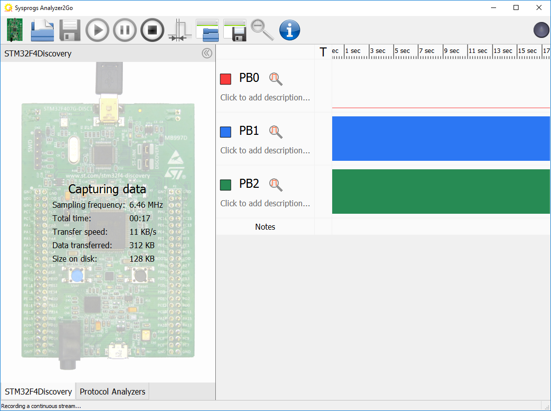
- After you plug in the second connector, Analyzer2Go will begin sampling the data. You can zoom and view the captured data while it is being captured, or simply stop it after several seconds:
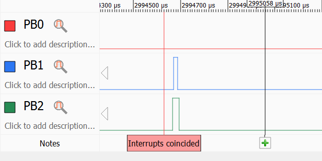
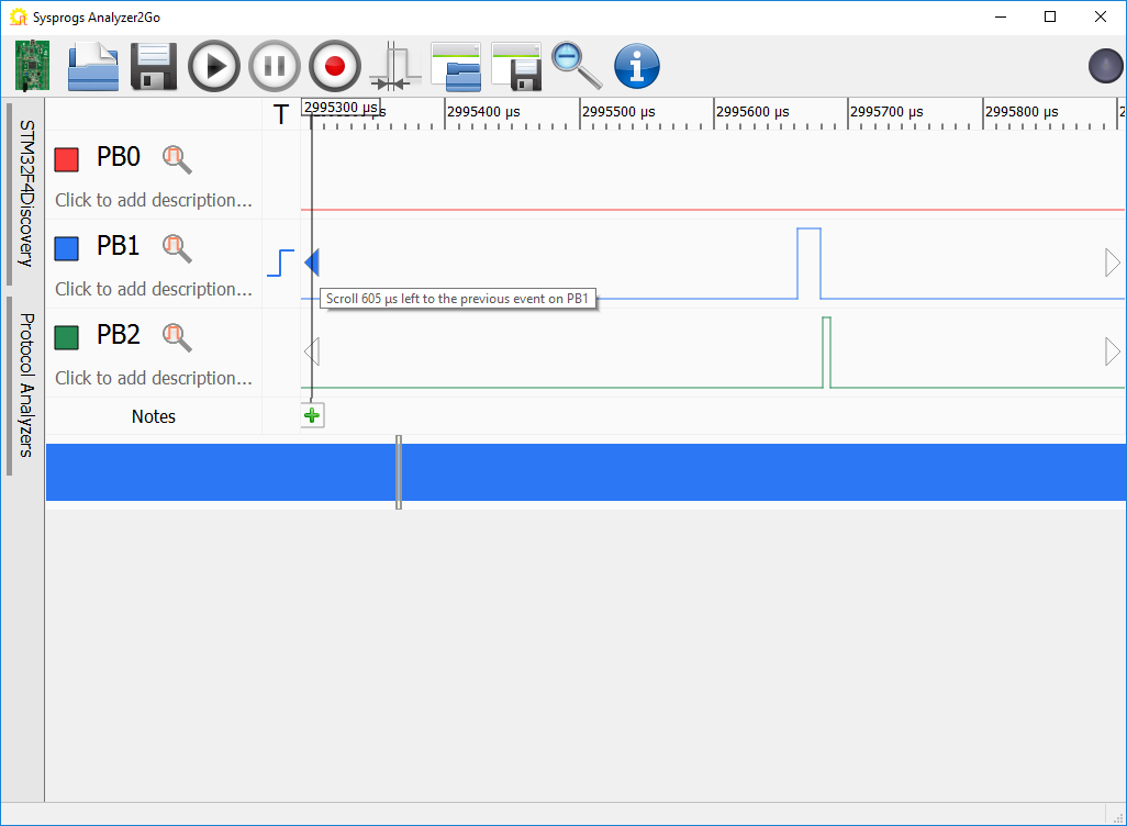
- Double-click on any of the signals to zoom to a meaningful scale. Then use the “previous event” and “next event” buttons to navigate to a point where the 2 interrupts happen close to each other:
- Once you locate that point, you can add a note to it using the “notes bar”. The note can be used later to quickly jump to that part of the capture file:
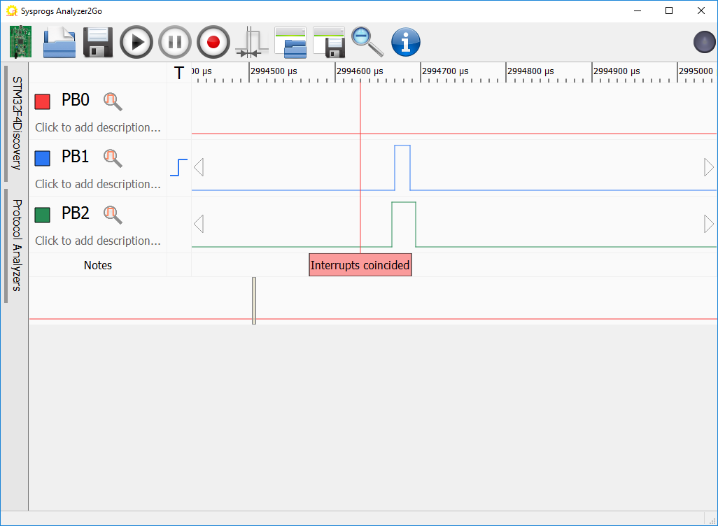 The captured data shows that the SysTick interrupt (green) is preempted by the TIM4 Interrupt (blue). I.e. if the TIM4 interrupt happens while the SysTick interrupt handler was already running, the SysTick interrupt handler will be invoked on top of it. Use the “Save button” to save the captured data (and the note) for further comparison.
 - Add the following code to the program to assigned higher priority to the TIM4 interrupt so that it won’t get preempted by SysTick:
    NVIC_SetPriority(TIM4_IRQn, 1);
    NVIC_SetPriority(SysTick_IRQn, 0);
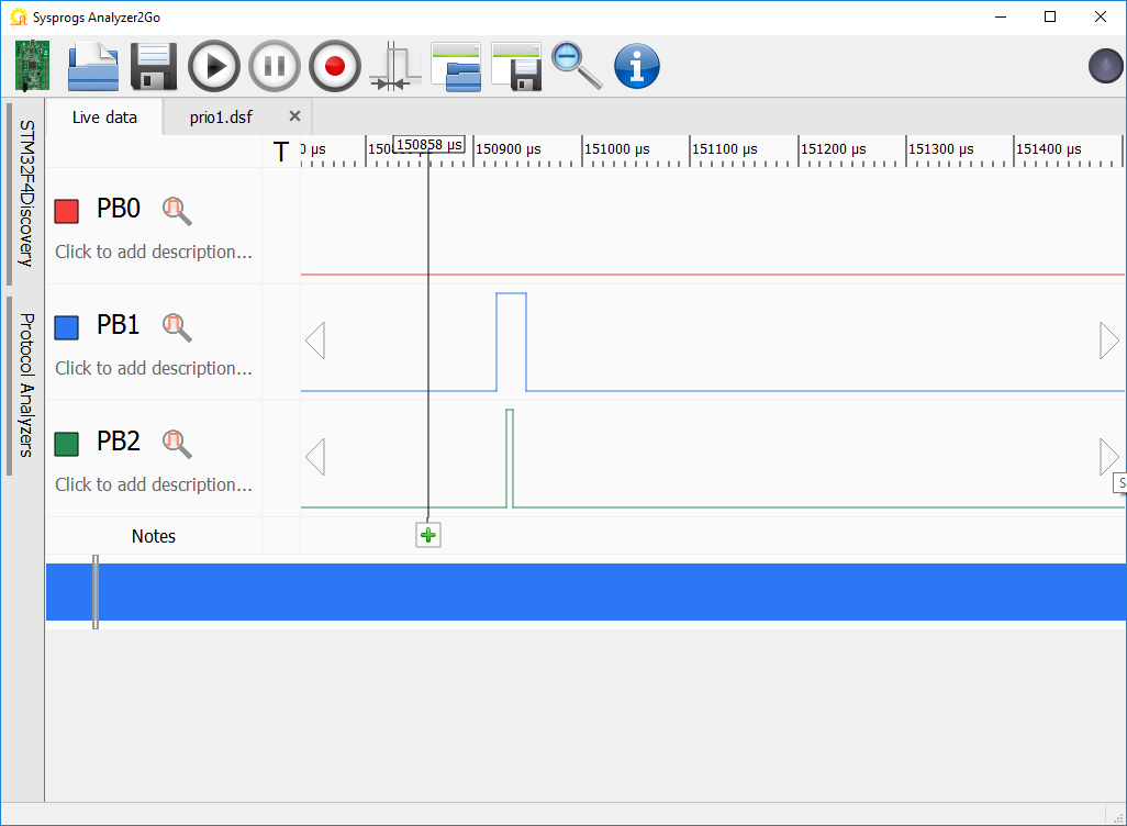
- Run another round of continuous capture to record the new timings and navigate to the point in time where the interrupts coincide. See how the SysTick interrupt (green) is now never preempted by the TIM4 interrupt (blue):
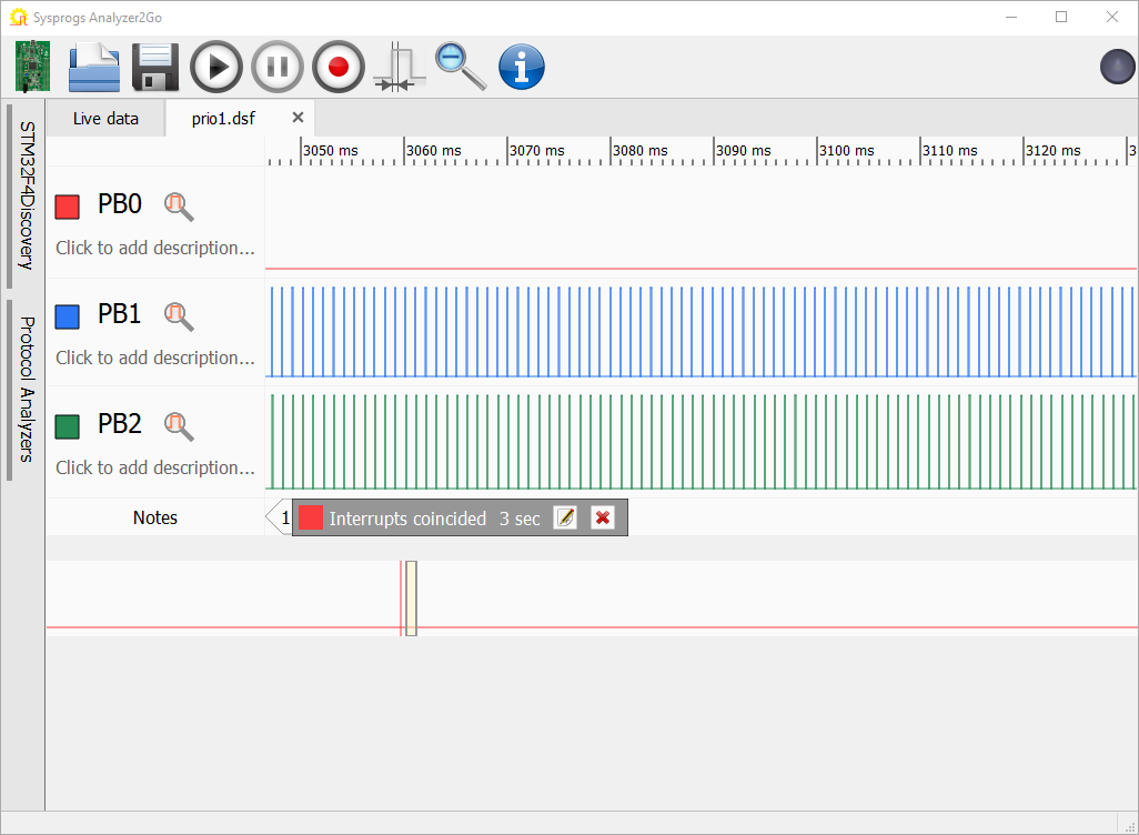
- You can switch back to the tab with the saved file to compare how the signals looked before and after. If you scroll out of the area where the interrupts coincided, use the “Notes” bar to quickly navigate back to it:
Starting from version 2.0 Analyzer2Go is compatible with the Cypress SuperSpeed Explorer Kit, supporting continuous capture at 200MHz via the fast USB 3.0 interface. Check out the SuperSpeed tutorial for details.