Decoding UART Output
In this tutorial we will show how to use Analyzer2Go to quickly decode the captured UART output. Before you begin, follow the basic Analyzer2Go tutorial to ensure it works with your hardware.
We will use 2 boards in this tutorial: one STM32F4Discovery board will run a simple program that picks a random number, prints it to UART and waits for the corresponding amount of milliseconds. The other STM32F4Discovery board controlled by Analyzer2Go will be used as a logic analyzer. We will use it to capture the UART output and verify that the actual delays match the expected ones.
Before you begin, compile and download the following program into the generator board:
UART_HandleTypeDef g_UART;
void GenerateUARTOutput()
{
    __USART2_CLK_ENABLE();
    __GPIOA_CLK_ENABLE();

    g_UART.Instance        = USART2;
    g_UART.Init.BaudRate   = 115200;
    g_UART.Init.WordLength = UART_WORDLENGTH_8B;
    g_UART.Init.StopBits   = UART_STOPBITS_1;
    g_UART.Init.Parity     = UART_PARITY_EVEN;
    g_UART.Init.HwFlowCtl  = UART_HWCONTROL_NONE;
    g_UART.Init.Mode       = UART_MODE_TX_RX;
    if (HAL_UART_Init(&g_UART) != HAL_OK)
        asm("bkpt 255");

    GPIO_InitTypeDef  GPIO_InitStruct;

    GPIO_InitStruct.Pin       = GPIO_PIN_3;
    GPIO_InitStruct.Mode      = GPIO_MODE_AF_PP;
    GPIO_InitStruct.Pull      = GPIO_PULLUP;
    GPIO_InitStruct.Speed     = GPIO_SPEED_HIGH;
    GPIO_InitStruct.Alternate = GPIO_AF7_USART2;

    HAL_GPIO_Init(GPIOA, &GPIO_InitStruct);

    GPIO_InitStruct.Pin = GPIO_PIN_2;
    GPIO_InitStruct.Alternate = GPIO_AF7_USART2;

    HAL_GPIO_Init(GPIOA, &GPIO_InitStruct);

    GPIO_InitStruct.Pin = GPIO_PIN_6;
    GPIO_InitStruct.Mode = GPIO_MODE_OUTPUT_PP;

    HAL_GPIO_Init(GPIOA, &GPIO_InitStruct);

    GPIO_InitStruct.Pin = GPIO_PIN_7;
    GPIO_InitStruct.Mode = GPIO_MODE_OUTPUT_PP;

    HAL_GPIO_Init(GPIOA, &GPIO_InitStruct);

    for (int i = 0;; i++)
    {
        char sz[128];
        int delay = rand() % 10;
        sprintf(sz, "Sleeping for %d msec...\n", delay);
        HAL_UART_Transmit(&g_UART, (unsigned char *)sz, strlen(sz), HAL_MAX_DELAY);
        HAL_GPIO_WritePin(GPIOA, GPIO_PIN_6, GPIO_PIN_SET);
        HAL_Delay(delay);
        HAL_GPIO_WritePin(GPIOA, GPIO_PIN_6, GPIO_PIN_RESET);
    }
}
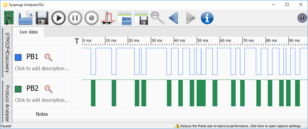
- Connect the UART signals (PA2/PA3) and the PA6 signal used to indicate the delay on the generator board to the inputs on the analyzer board and start Analyzer2Go. Enable signal capture on the channels you connected. You will see the randomly looking pulses on the PA6 and tightly packed sequences of pulses on the UART channel:
- Zoom in using the mouse wheel or by double-clicking on one of the pulse packs:
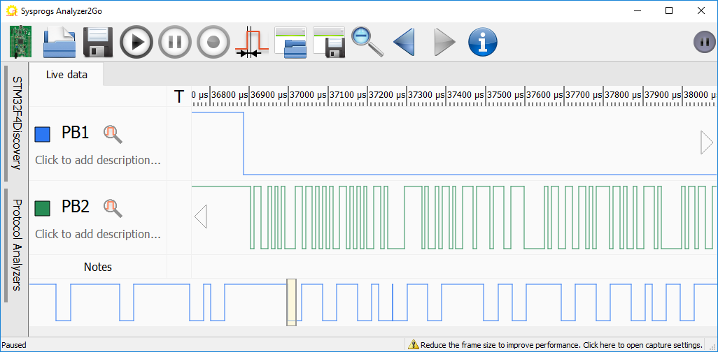
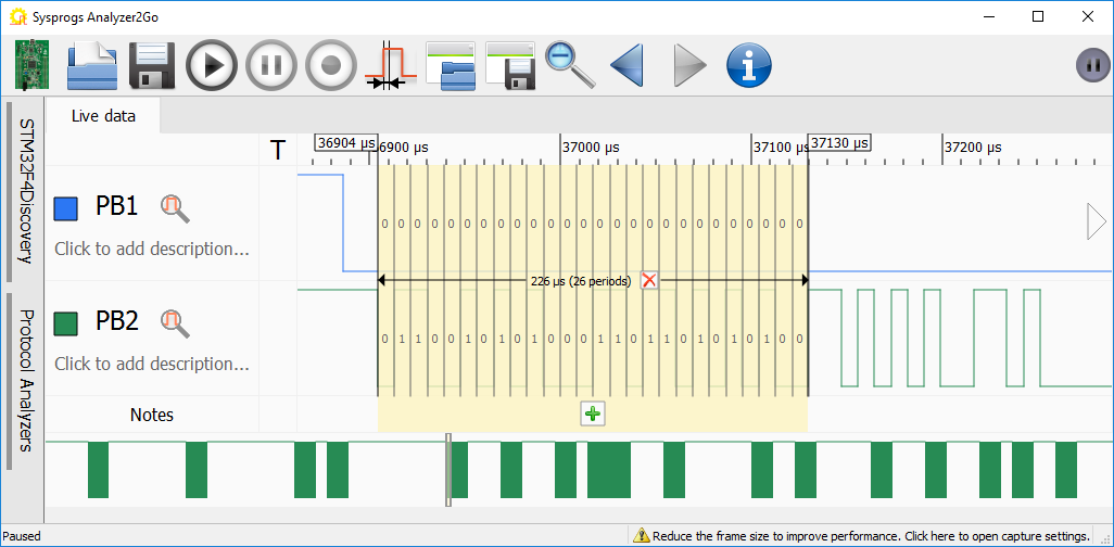
- The lower signal (PB2 in this example) is the UART output. You can get a low-level insight into it by selecting the shortest pulse and clicking the “1” icon to set its length as a reference pulse length:
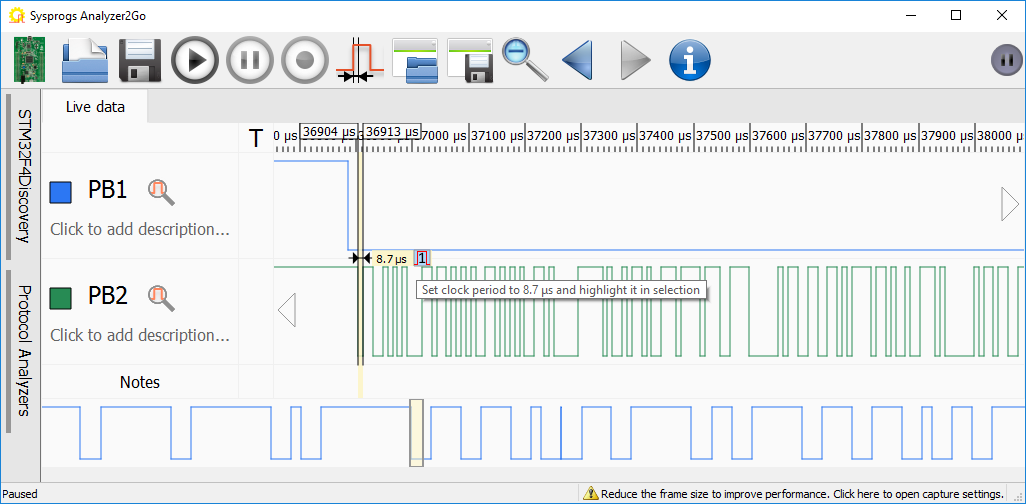
- If you now select any portion of the UART output, Analyzer2Go will automatically split it into single bits based on the previously selected period and will display their values (e.g. 0 11001010 corresponds to a start bit followed by a value of 0x53 representing the capital ‘S’ letter):
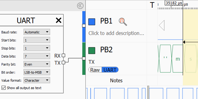
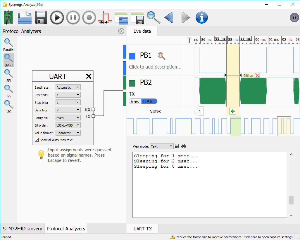
- While looking at the bits manually may be useful for diagnosing complex timing issues, in most of the cases it would be unnecessary complex. Analyzer2Go provides a convenient mechanism of decoding the output manually. First, change the description of the PB2 signal to ‘TX’ so that Analyzer2Go can guess its meaning from the name. Then go to the Protocol Analyzers page and drag-and-drop the UART analyzer in the work area:
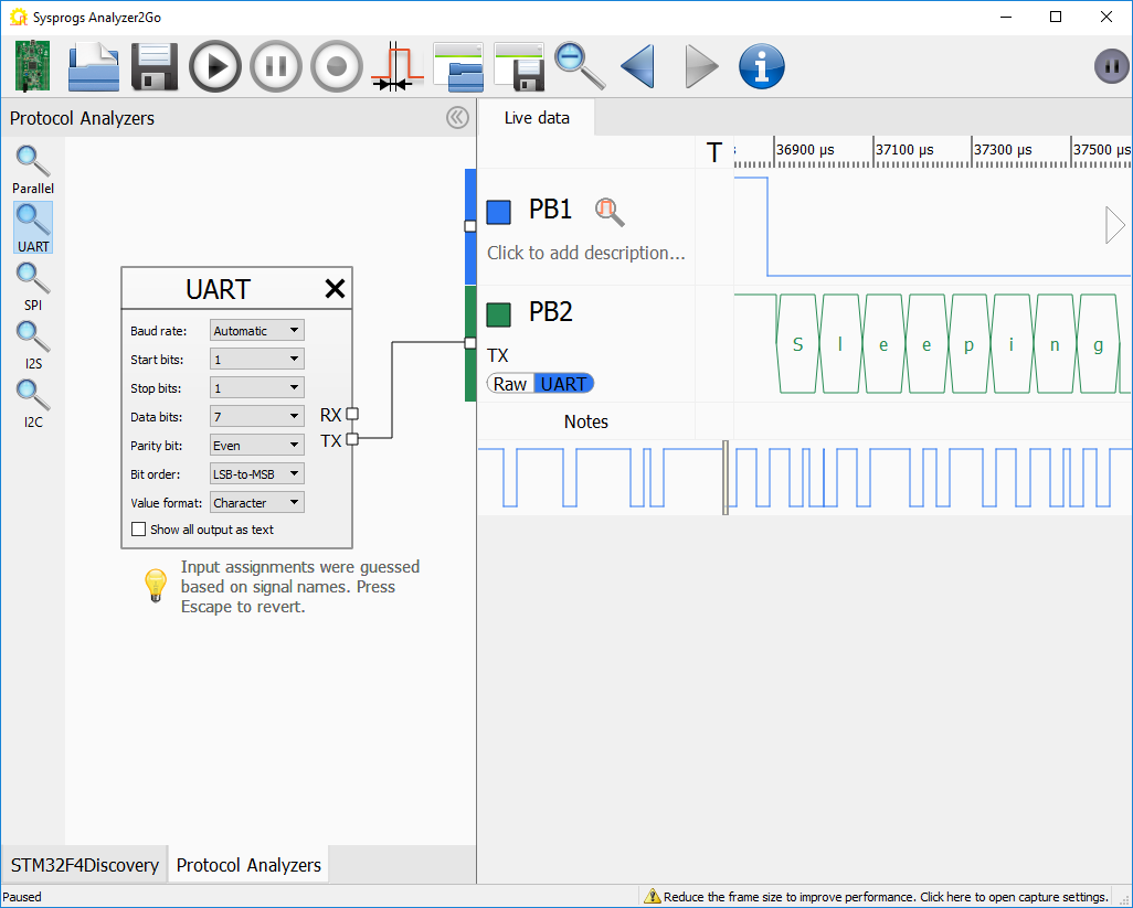 It will automatically recognize the “TX” input and replace the raw signal there with decoded UART values.
 - You can change various decoder settings (e.g. parity mode) in the Protocol Analyzers pane. Check the “Show all output as text” checkbox to automatically decode all of the UART output within the captured frame:
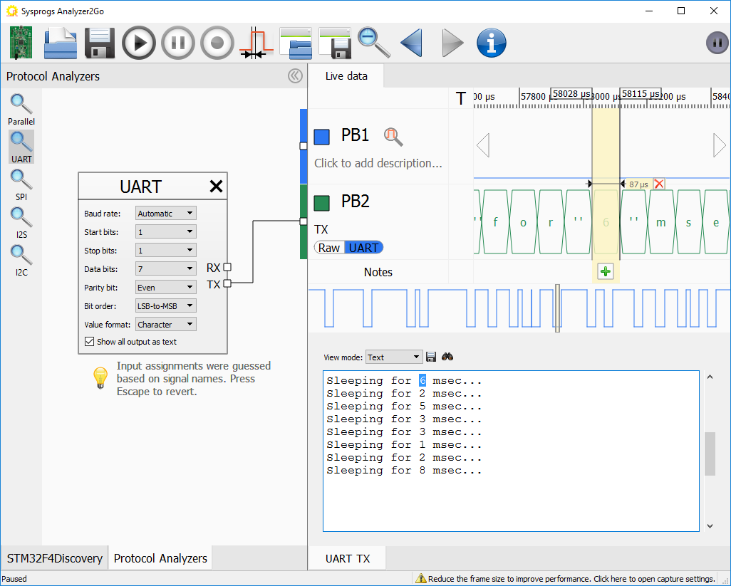 Note how selecting text in the text area will automatically select the corresponding time span in the signal view.
 - Select the pause after the “6 msec” message to verify that the board actually slept for 6 milliseconds:
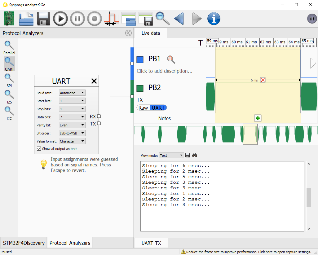
- You can mark the checked area by adding a note to it (click the ‘add note’ button in the note bar):
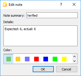
- The note will be displayed in the scroll bar and in the signal view:
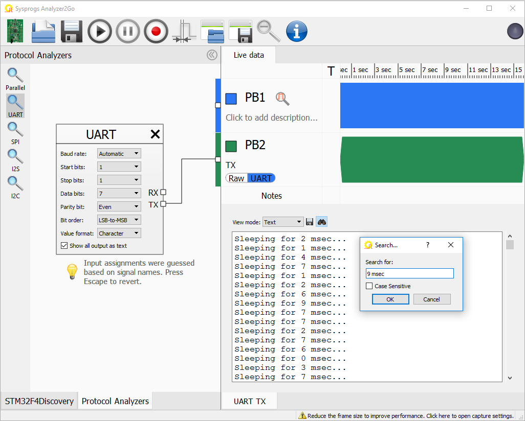
- If your signal does not require more bandwidth than the capturing board can provide, you can use the continuous capture mode to record gigabytes of logs. The protocol analyzers are optimized to work fast with large capture files and the text view will allow quickly looking through the captured output:
- Use the “Search” button to find events in the decoded output. The search is optimized to handle very large files and will run in the background:
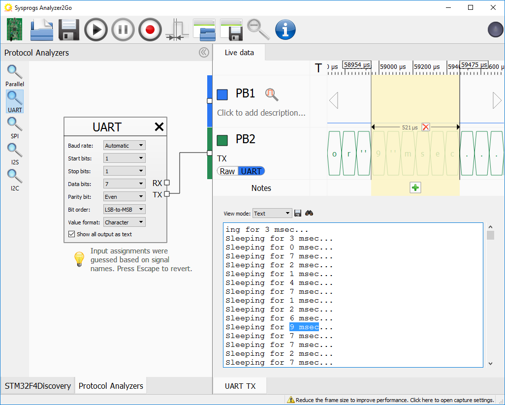
- Once the message is found, Analyzer2Go will highlight it in both the text view and the signal view so you can quickly lookup other nearby events:
Starting from version 2.0 Analyzer2Go is compatible with the Cypress SuperSpeed Explorer Kit, supporting continuous capture at 200MHz via the fast USB 3.0 interface. Check out the SuperSpeed tutorial for details.