Using Triggers to Synchronize Captured Signals
This tutorial shows how to use triggers to capture the signal values around the interesting events. Before you begin, follow the basic Analyzer2Go tutorial to get started with Analyzer2Go.
We will use 2 STM32F4Discovery boards: one will generate a basic signal using its GPIO ports and the other one will be used by Analyzer2Go as a logic analyzer to capture the signals. We will run the following program on the first board:
    __GPIOD_CLK_ENABLE();
    GPIO_InitTypeDef GPIO_InitStructure;

    GPIO_InitStructure.Pin = GPIO_PIN_12 | GPIO_PIN_13 | GPIO_PIN_14;

    GPIO_InitStructure.Mode = GPIO_MODE_OUTPUT_PP;
    GPIO_InitStructure.Speed = GPIO_SPEED_HIGH;
    GPIO_InitStructure.Pull = GPIO_NOPULL;
    GPIO_InitStructure.Alternate = GPIO_AF2_TIM4;
    HAL_GPIO_Init(GPIOD, &GPIO_InitStructure);

    for (;;)
    {
        HAL_GPIO_WritePin(GPIOD, GPIO_PIN_12, GPIO_PIN_SET);
        for (int i = 0; i < 100; i++)
        {
            HAL_GPIO_WritePin(GPIOD, GPIO_PIN_13, GPIO_PIN_SET);
            HAL_GPIO_WritePin(GPIOD, GPIO_PIN_13, GPIO_PIN_RESET);
        }
        HAL_GPIO_WritePin(GPIOD, GPIO_PIN_12, GPIO_PIN_RESET);
        for (int i = 0; i < 100000; i++)
            asm("nop");
    }
The program will generate a positive edge on PD12 followed by 100 pulses on PD13. We will use Analyzer2Go to see how uniform the generated signal will be.
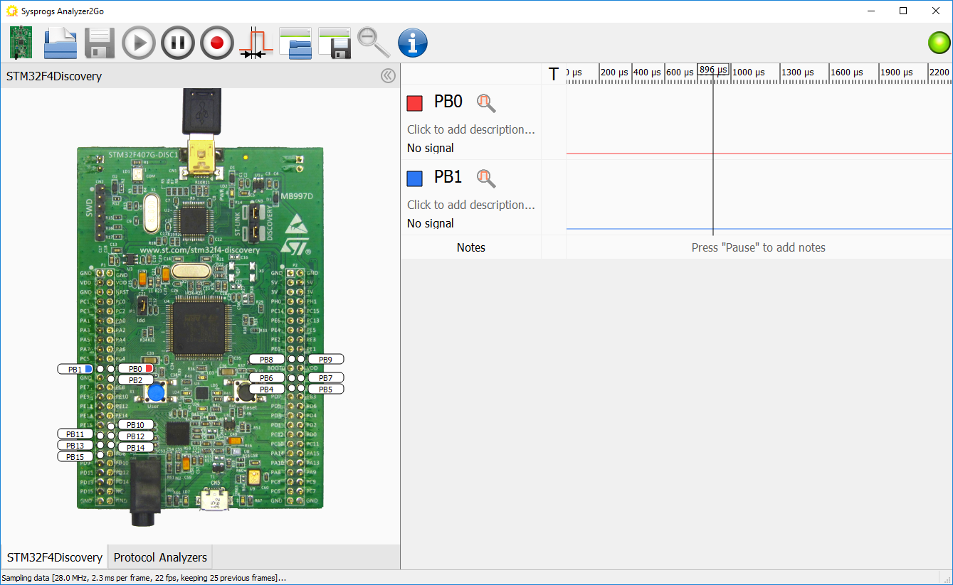
- Start Analyzer2Go and select your board type. Then load the program shown below into the generator board and connect the PD12 and PD13 signals on it to the inputs on the second board. Analyzer2Go will show that for most of the time both signals are idle and sometimes a short sequence of pulses appears:
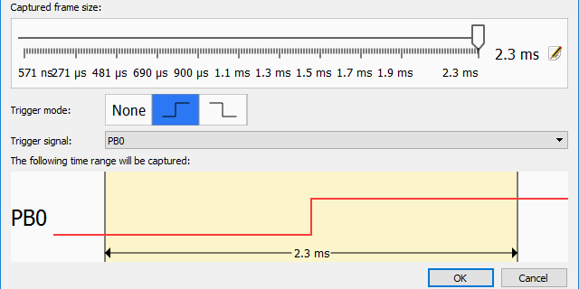
- As we are only interested in the signals inside the 100-pulse sequence, we will set a rising edge trigger on the signal that goes high before the pack and low after it. To do that, simply click in the “T” column of the corresponding row:
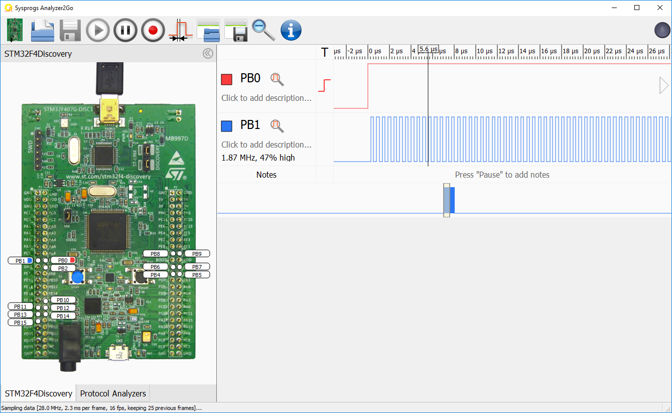 Analyzer2Go will now capture the signals exactly around each rising pulse. The trigger mechanism is designed to capture even very rare events – once it starts waiting for a trigger, it will keep recording and discarding the data on all channels. Once the trigger is detected, the captured data will be aligned so that the trigger is exactly in the middle of it. As a result, you will see a quick sequence of frames, each one centered around the trigger pulse.
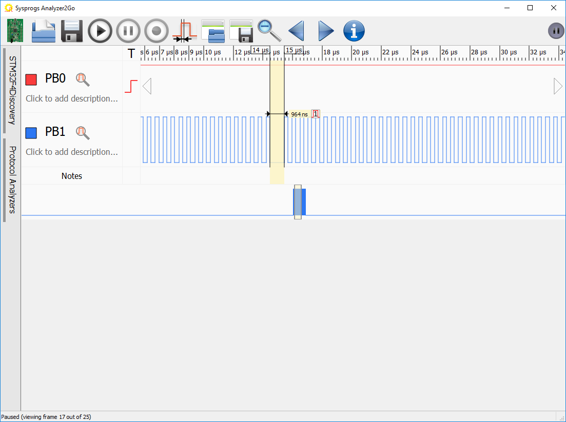
 - You will notice that once in a while it looks like the 100-pulse signal is slightly irregular. You can study it by pressing “Pause” and navigating back to the irregular frame using the “Back” button:
- You can select the irregular pulse to measure its length:
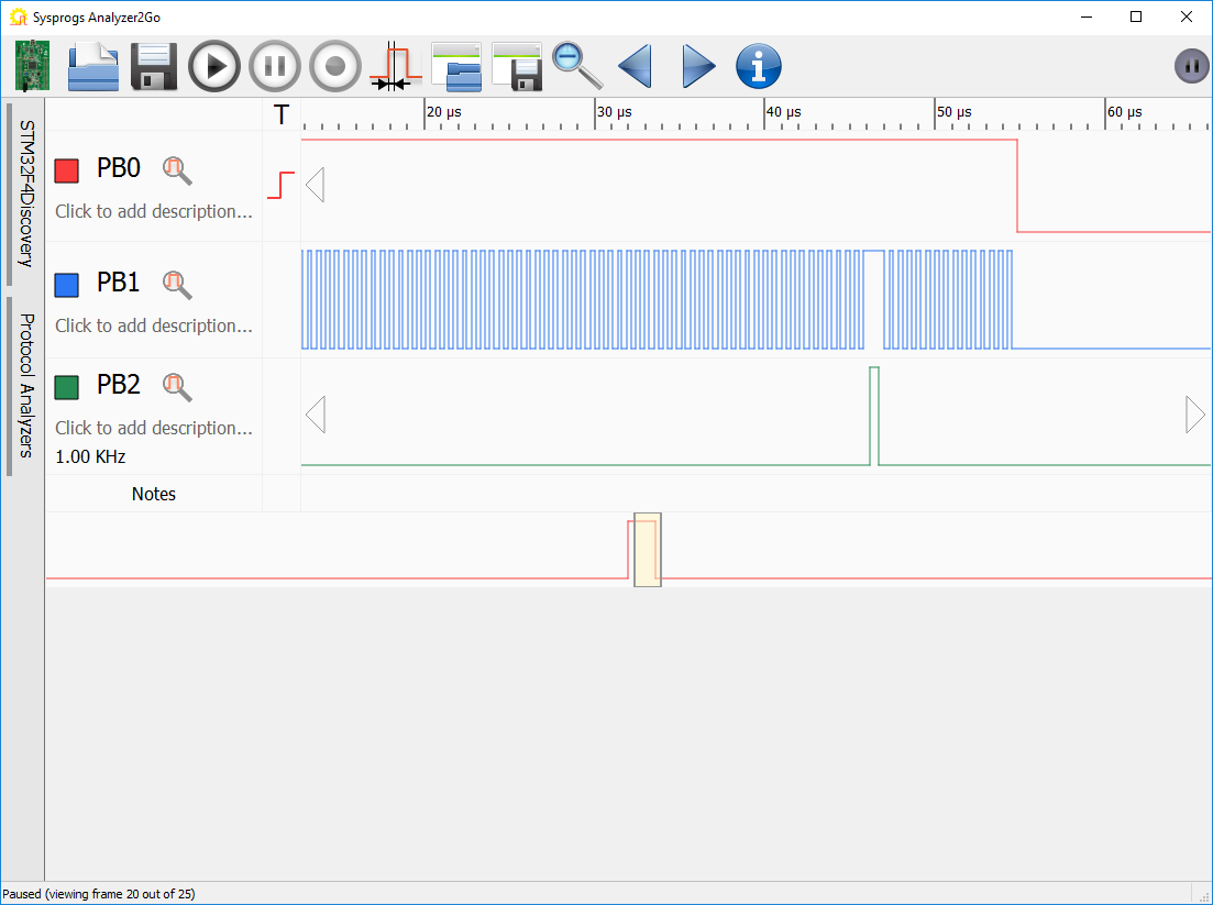
- The irregular pulse generated by the board might be caused by the CPU handing interrupts. You can verify it by configuring the interrupt handler to set another signal to 1 on entry and reset it back to 0 on exit:
void SysTick_Handler(void) { HAL_GPIO_WritePin(GPIOD, GPIO_PIN_14, GPIO_PIN_SET); HAL_IncTick(); HAL_SYSTICK_IRQHandler(); HAL_GPIO_WritePin(GPIOD, GPIO_PIN_14, GPIO_PIN_RESET); } - Upload the modified code to the generator board and capture the extra signal. You will see that the lag always coincides with the timer interrupt:
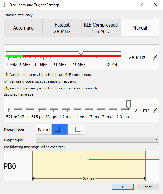
- You can use the Frequency and Trigger Settings button to review and change the trigger settings used by Analyzer2Go:
Starting from version 2.0 Analyzer2Go is compatible with the Cypress SuperSpeed Explorer Kit, supporting continuous capture at 200MHz via the fast USB 3.0 interface. Check out the SuperSpeed tutorial for details.