Capturing Large Volumes of Data with the Super Speed Explorer Kit
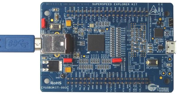
This tutorial shows how to use the Cypress Super Speed Explorer Kit board to capture and analyze large amounts of data using Analyzer2Go. We will create a basic project for the STM32F4Discovery board that will generate large amounts of UART data at ~8M bits per second and will show how to capture it at a fast 200MHz sampling rate, analyze various timings and extract the transmitted text.
Before you begin, connect the following inputs of the 2 boards:
| STM32F4Discovery pin | SuperSpeed Explorer Kit pin |
|---|---|
| GND | GND |
| PA2 | DQ0 |
| PE0 | DQ1 |
| PE1 | DQ2 |
| PE2 | DQ3 |
| PE3 | DQ4 |
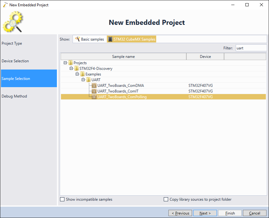
- We will start with creating a basic project for the STM32F4Discovery board that will generate the fast UART output (pin PA2) and cycle values from 0000 (0x0) to 1111 (0xF) via 4 parallel pins (PE0 to PE3). The easiest way to do this is to start Visual Studio with VisualGDB and clone the UART_TwoBoards_ComPolling sample:
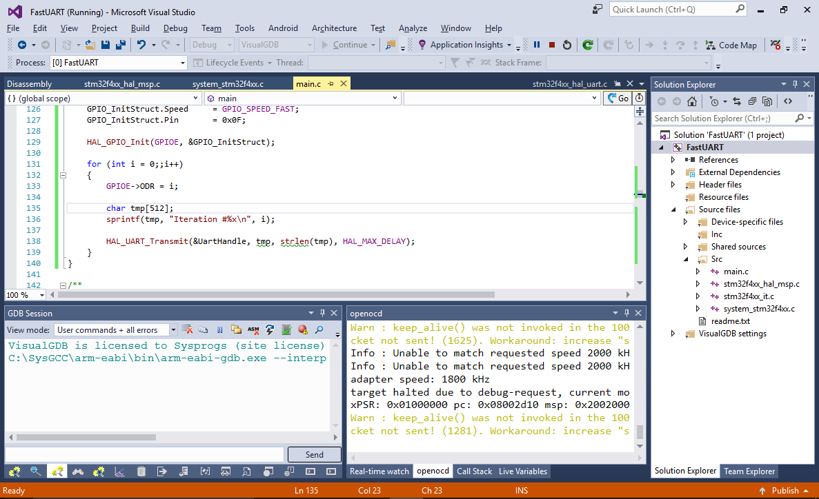
- Once the sample is created, replace the code in the main() function with the following:
int main(void)
{

 /* STM32F4xx HAL library initialization:
 - Configure the Flash prefetch, instruction and Data caches
 - Configure the Systick to generate an interrupt each 1 msec
 - Set NVIC Group Priority to 4
 - Global MSP (MCU Support Package) initialization
 */
 HAL_Init();

 /* Configure LED3, LED4, LED5 and LED6 */
 BSP_LED_Init(LED3);
 BSP_LED_Init(LED4);
 BSP_LED_Init(LED5);
 BSP_LED_Init(LED6);

 /* Configure the system clock to 168 MHz */
 SystemClock_Config();

 /*##-1- Configure the UART peripheral ######################################*/
 /* Put the USART peripheral in the Asynchronous mode (UART Mode) */
 /* UART1 configured as follow:
 - Word Length = 8 Bits
 - Stop Bit = One Stop bit
 - Parity = None
 - BaudRate = 9600 baud
 - Hardware flow control disabled (RTS and CTS signals) */
 UartHandle.Instance = USARTx;

 UartHandle.Init.BaudRate = 115200 * 64;
 UartHandle.Init.WordLength = UART_WORDLENGTH_8B;
 UartHandle.Init.StopBits = UART_STOPBITS_1;
 UartHandle.Init.Parity = UART_PARITY_NONE;
 UartHandle.Init.HwFlowCtl = UART_HWCONTROL_NONE;
 UartHandle.Init.Mode = UART_MODE_TX_RX;
 UartHandle.Init.OverSampling = UART_OVERSAMPLING_8;

 if (HAL_UART_Init(&UartHandle) != HAL_OK)
 {
 Error_Handler();
 }

 __GPIOE_CLK_ENABLE();
 GPIO_InitTypeDef GPIO_InitStruct;

 /* UART TX GPIO pin configuration */
 GPIO_InitStruct.Mode = GPIO_MODE_OUTPUT_PP;
 GPIO_InitStruct.Pull = GPIO_NOPULL;
 GPIO_InitStruct.Speed = GPIO_SPEED_FAST;
 GPIO_InitStruct.Pin = 0x0F;

 HAL_GPIO_Init(GPIOE, &GPIO_InitStruct);

 for (int i = 0;;i++)
 {
 GPIOE->ODR = i;

 char tmp[512];
 sprintf(tmp, "Iteration #%x\n", i);

 HAL_UART_Transmit(&UartHandle, tmp, strlen(tmp), HAL_MAX_DELAY);
 }
}
Also adjust the APB1 clock divider in SystemClock_Config() to be equal to 2:
RCC_ClkInitStruct.APB1CLKDivider = RCC_HCLK_DIV2;
- Finally press F5 to build the project and start running it:
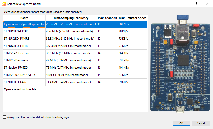
- The code will start running and will generate the UART output at approximately 7.76M bits per second (the baud rate will be rounded to the nearest divided peripheral clock). Now we will show how to capture and analyze this data with Analyzer2Go. Ensure your SuperSpeed Explorer kit is connected to a USB 3.0 SuperSpeed port and start Analyzer2Go. Select the board and press OK:
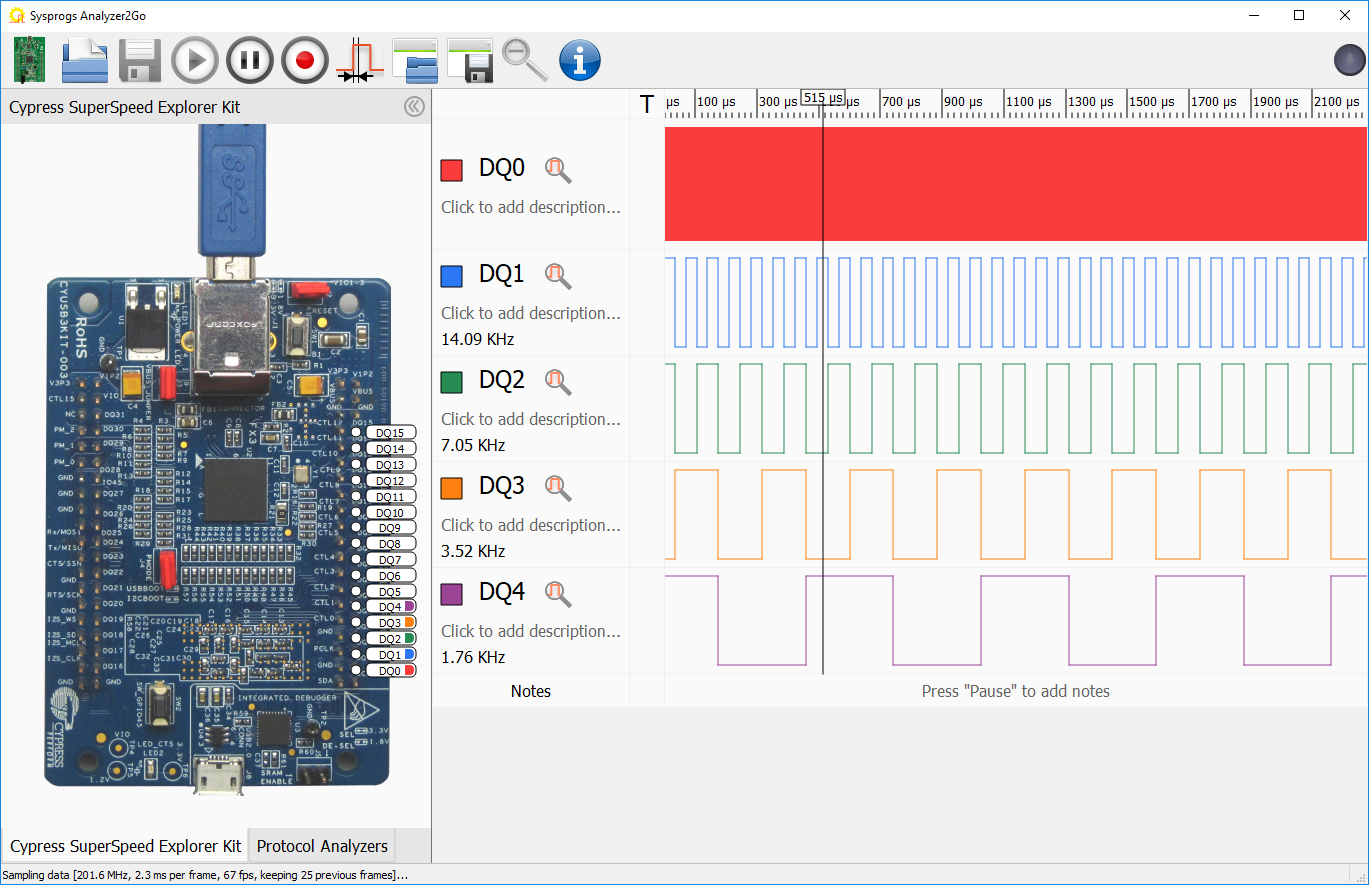
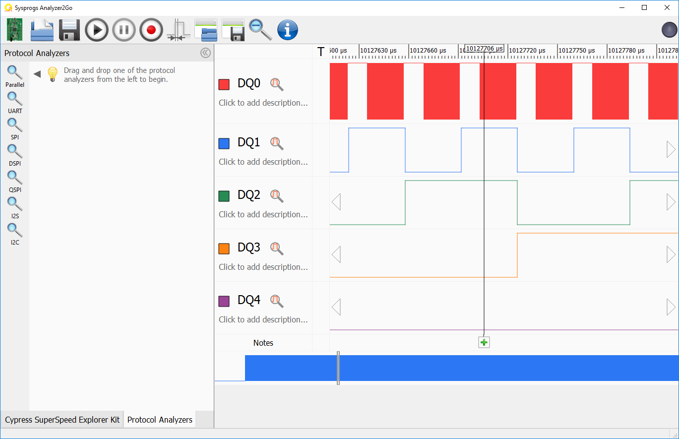
- Begin sampling the DQ0 to DQ4 ports. You will immediately see the fast UART output and the looped pattern in the DQ1-DQ4 inputs (as the firmware is outputting numbers from 0 to 0x0F in a parallel way, each higher bit is toggled twice slower than the lower bit):
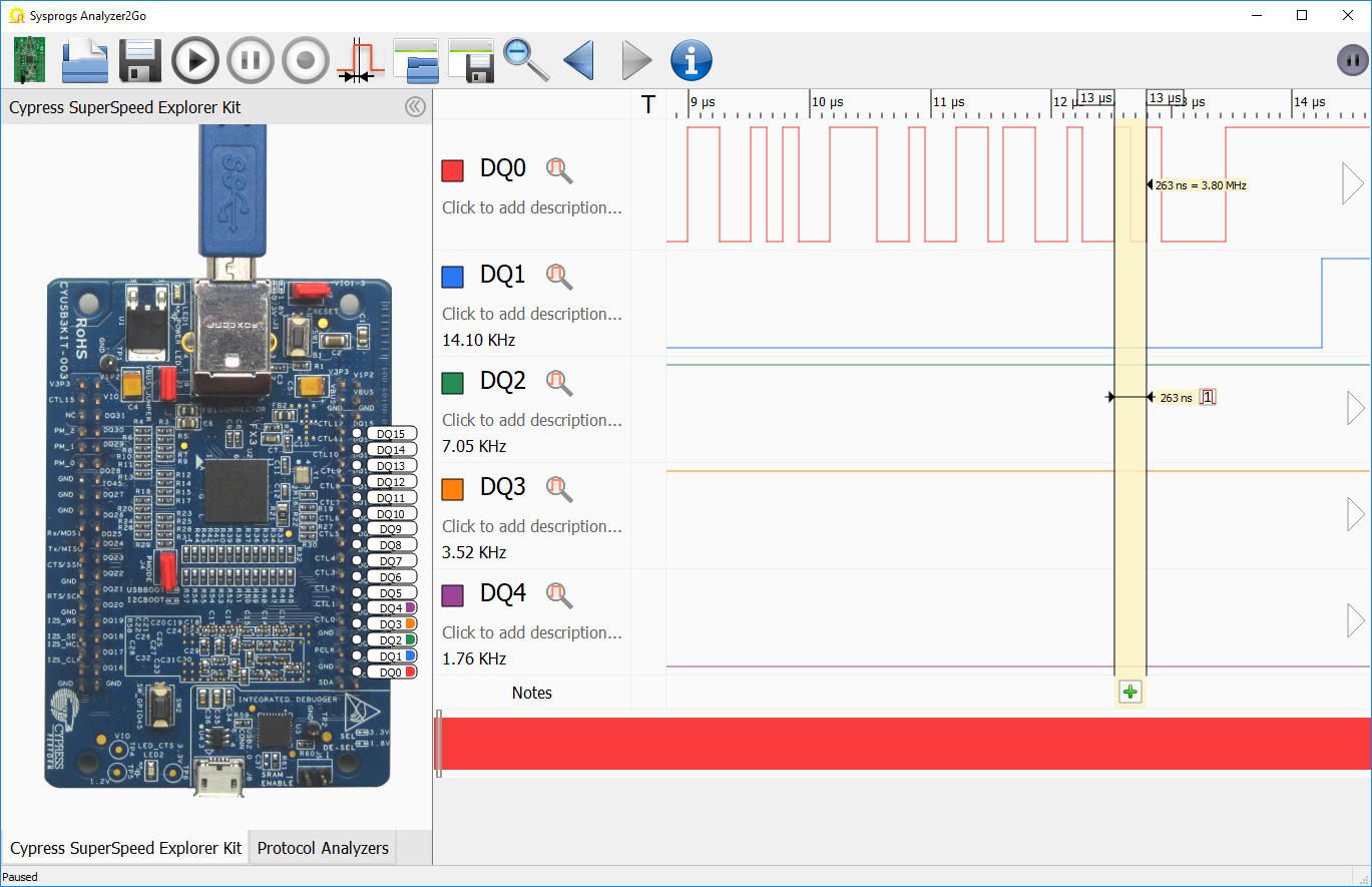
- Normally Analyzer2Go will only capture 1 frame at a time as it allows seeing the signal changes immediately. Press the “pause” button, zoom to the UART signal and select one full cycle. Analyzer2Go will compute the signal period (and the corresponding frequency). Note that the baud rate will be twice the shown frequency as one period includes 2 bits:
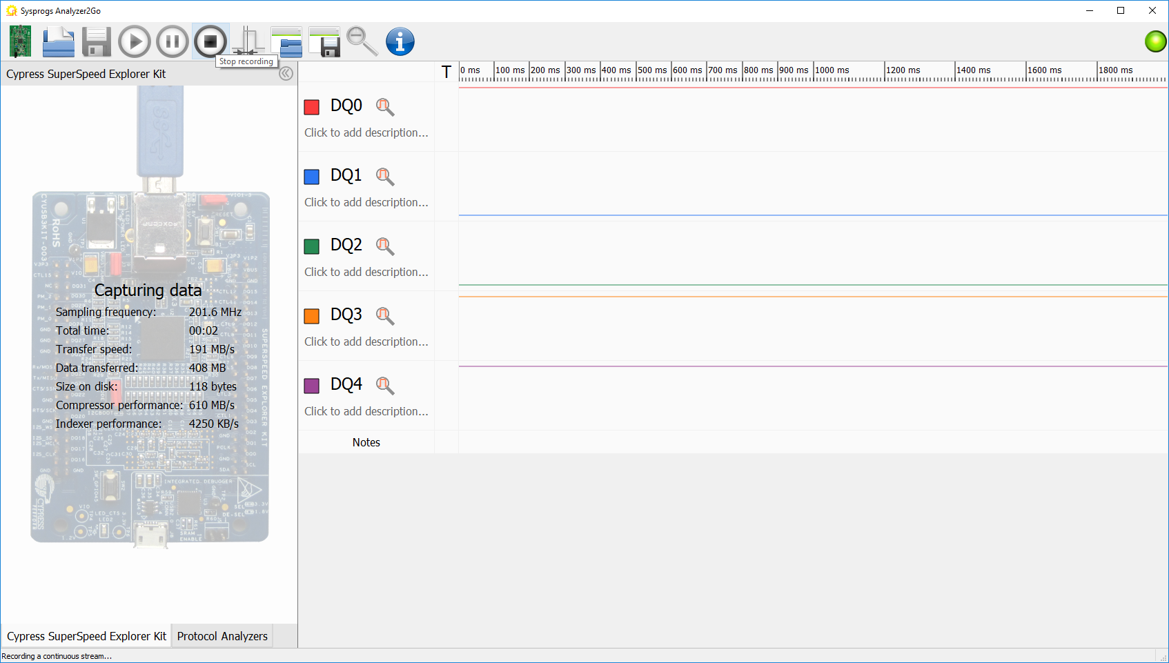
- Now we will show how to record a large amount of data. Press and hold the Reset button on the STM32F4Discovery board to ensure we capture the very first moments after reset and click the Record button in Analyzer2Go. It will begin making a continuous recording and will display statistics to the left from the signals:
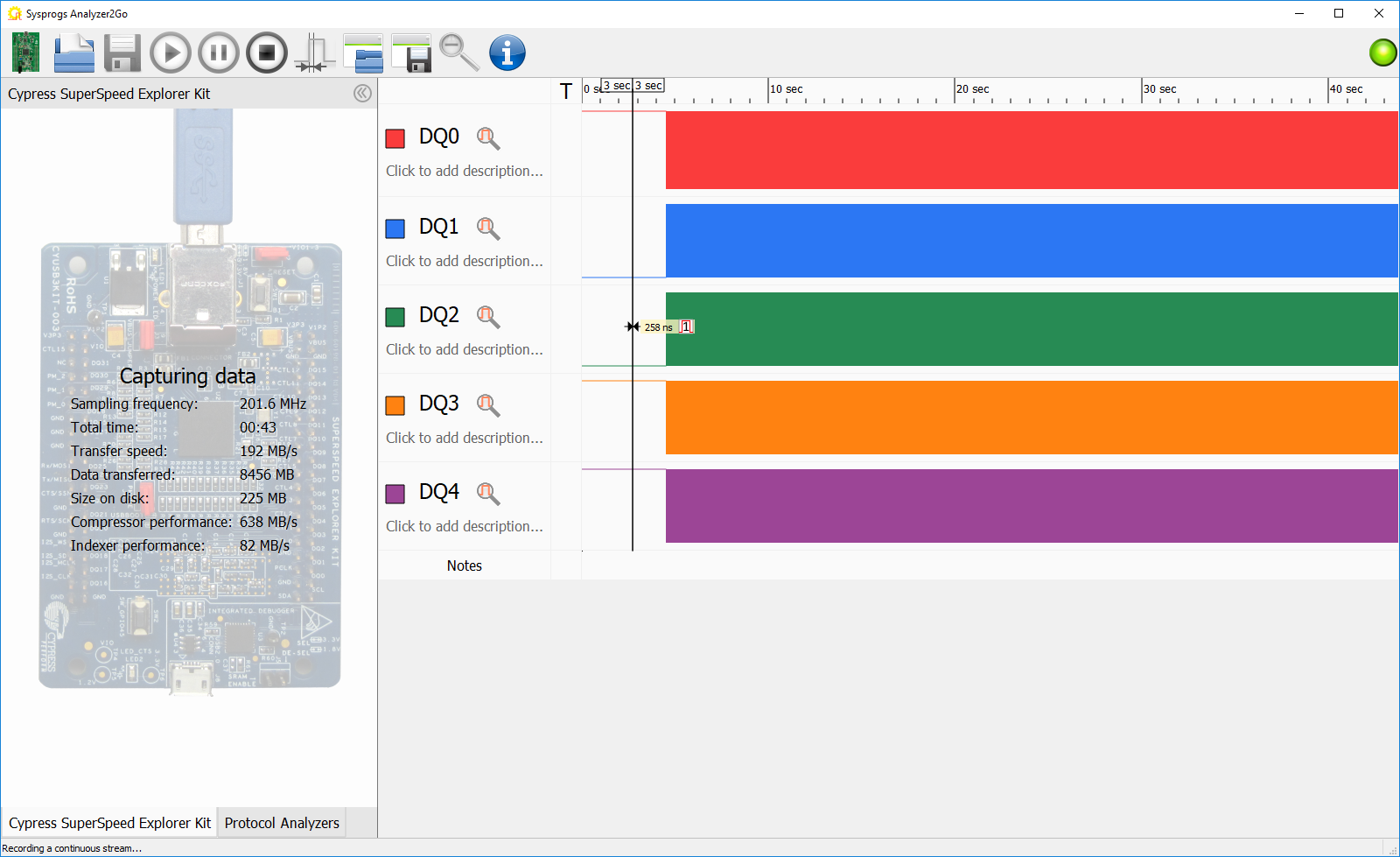
- Release the reset button on the STM32F4Discovery board so that it will begin generating data. Once you record sufficient data, click the Stop button in Analyzer2Go:
 Analyzer2Go is optimized to handle huge amounts of data coming from the SuperSpeed Explorer Kit board (up to 200 MHz sampling rate when using 8 channels and up to 100 MHz when using 16 channels). It will use all available CPU cores to compress it on-the-fly and will use all the available RAM (exceeding the 4GB limit if needed) to buffer the data if it’s coming too fast to be processed.
 - Once the recording is complete, zoom into an arbitrary portion of the graph. See how the period signal changes relatively slowly with packets of fast UART output between the changes:
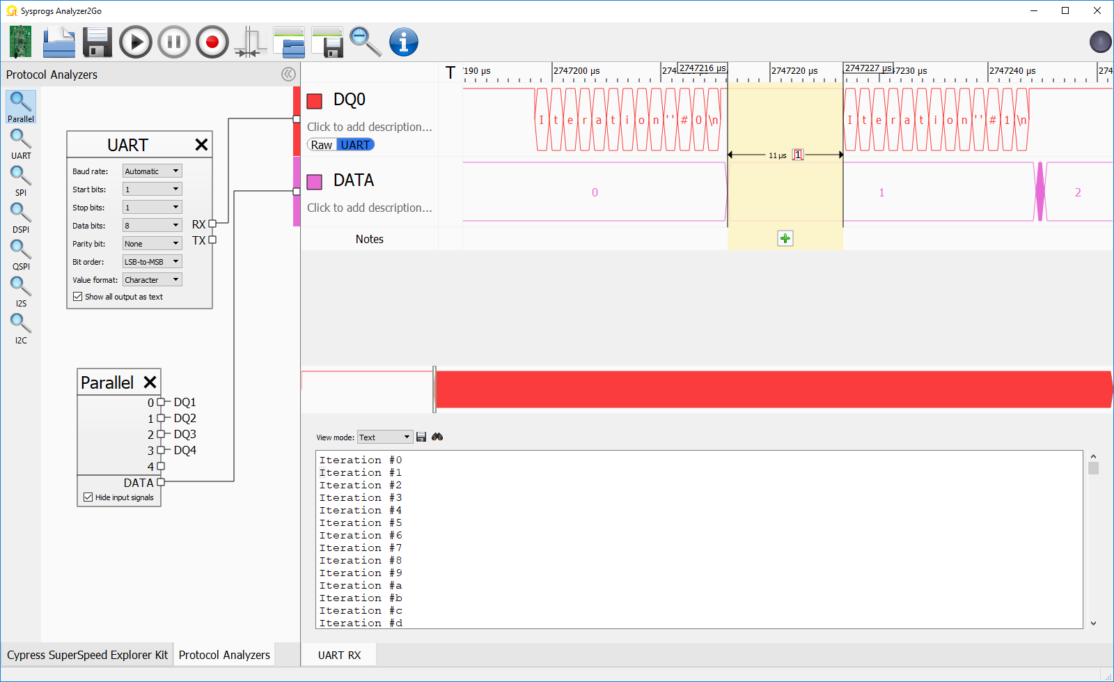
- In order to interpret this data, switch to the “Protocol Analyzers” tab and add the UART and Parallel analyzers. Connect the UART analyzer to the DQ0 channel and the Parallel analyzer to the remaining channels. Analyzer2Go will now display meaningful text instead of the raw UART waveform. See how the last hex digit of the message matches the value from the parallel pins:
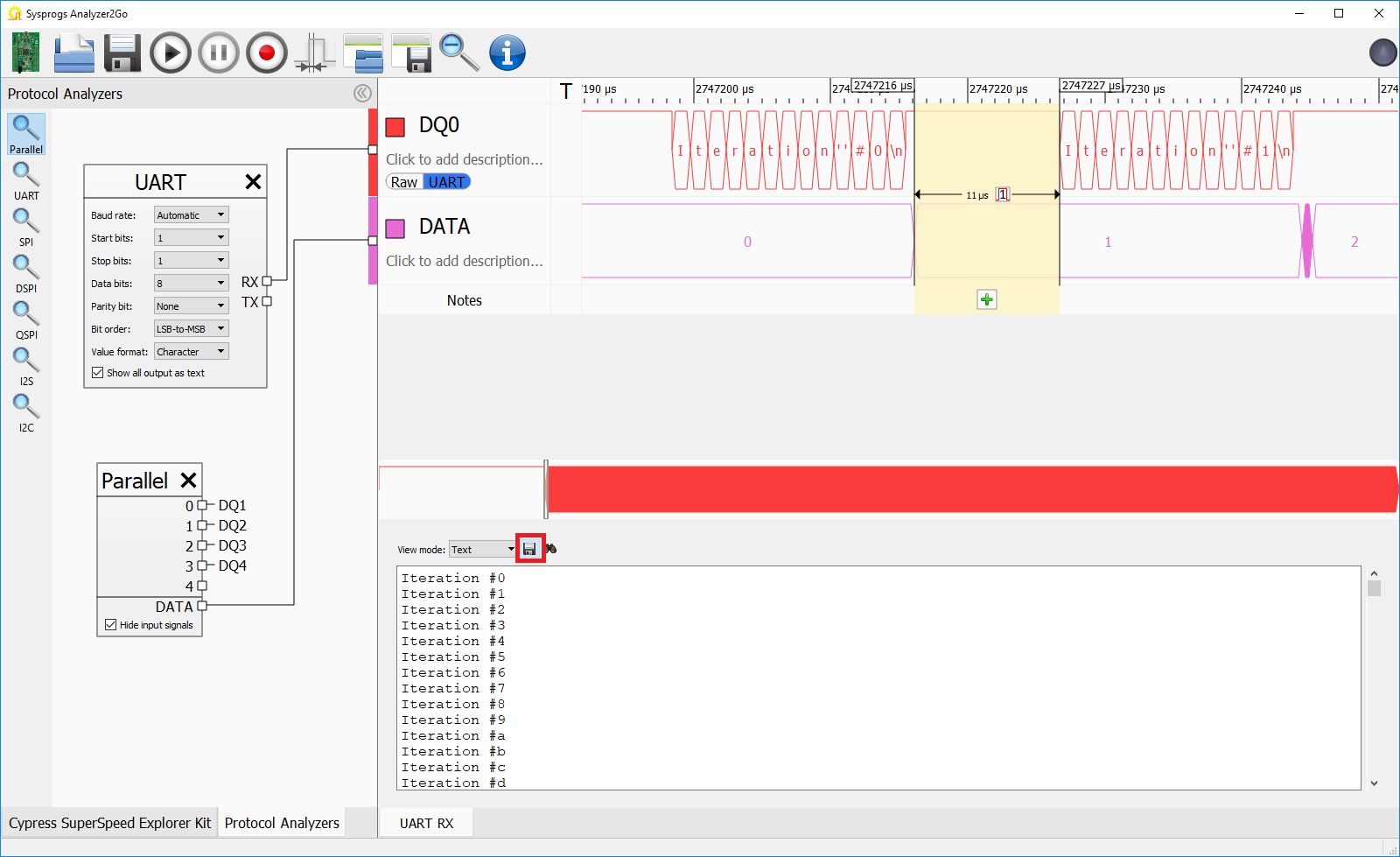
- You can export the text recovered from the UART port by clicking the “Save” button and see that it contains “Iteration XXX” lines just as expected:
 You can also use the “Save Captured Data” button to save the raw captured data. Once saved, you can open it later, change the protocol analyzer settings, or save notes attached to various parts of the graphs.