Capturing Basic Signals with Analyzer2Go
This tutorial shows how to use Analyzer2Go to capture and quickly analyze a basic digital signal. We will use an STM32F4Discovery board to produce 2 different periodic signals with a timer and use Analyzer2Go to capture and visualize them using another STM32F4Discovery board as a logic analyzer.
Warning! STM32 boards are not 5V-tolerant. If you want to sample 5V logic with them, use a voltage divider.
Before you begin, compile and upload a program with the following code to generate 3 signals on the channels 1-3 of timer #4
static TIM_HandleTypeDef s_Timer = {
        .Instance = TIM4
    };

    int prescaler = 16;
    int period = 8;
    unsigned pulseLength = 1;

    __TIM4_CLK_ENABLE();
    s_Timer.Init.Prescaler = prescaler - 1;
    s_Timer.Init.CounterMode = TIM_COUNTERMODE_UP;
    s_Timer.Init.Period = period - 1;
    s_Timer.Init.ClockDivision = TIM_CLOCKDIVISION_DIV1;
    s_Timer.Init.RepetitionCounter = 0;

    TIM_OC_InitTypeDef oc = {
        .OCMode = TIM_OCMODE_PWM1,
        .Pulse = pulseLength,
        .OCPolarity = TIM_OCPOLARITY_HIGH,
        .OCNPolarity = TIM_OCPOLARITY_HIGH,
        .OCFastMode = TIM_OCFAST_DISABLE,
        .OCIdleState = TIM_OCIDLESTATE_SET
    };

    if (HAL_TIM_OC_Init(&s_Timer) != HAL_OK)
        asm("bkpt 255");
    if (HAL_TIM_OC_ConfigChannel(&s_Timer, &oc, TIM_CHANNEL_1) != HAL_OK)
        asm("bkpt 255");
    if (HAL_TIM_OC_Start(&s_Timer, TIM_CHANNEL_1) != HAL_OK)
        asm("bkpt 255");

    oc.OCMode = TIM_OCMODE_PWM2;

    if (HAL_TIM_OC_ConfigChannel(&s_Timer, &oc, TIM_CHANNEL_2) != HAL_OK)
        asm("bkpt 255");
    if (HAL_TIM_OC_Start(&s_Timer, TIM_CHANNEL_2) != HAL_OK)
        asm("bkpt 255");

    oc.OCMode = TIM_OCMODE_TOGGLE;

    if (HAL_TIM_OC_ConfigChannel(&s_Timer, &oc, TIM_CHANNEL_3) != HAL_OK)
        asm("bkpt 255");
    if (HAL_TIM_OC_Start(&s_Timer, TIM_CHANNEL_3) != HAL_OK)
        asm("bkpt 255");

    __GPIOD_CLK_ENABLE();
    GPIO_InitTypeDef GPIO_InitStructure;

    GPIO_InitStructure.Pin = GPIO_PIN_12 | GPIO_PIN_13 | GPIO_PIN_14;

    GPIO_InitStructure.Mode = GPIO_MODE_AF_PP;
    GPIO_InitStructure.Speed = GPIO_SPEED_HIGH;
    GPIO_InitStructure.Pull = GPIO_NOPULL;
    GPIO_InitStructure.Alternate = GPIO_AF2_TIM4;
    HAL_GPIO_Init(GPIOD, &GPIO_InitStructure);
- Connect the board you want to use as a logic analyzer to your computer (only the ST-Link connection is required) and start Analyzer2Go. Then select your board type from the list:
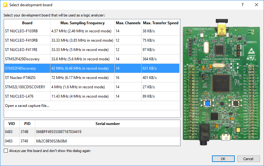
If Analyzer2Go detects several instances of the same board type, it will show the serial numbers so that you can select a specific one from the list. - When you press OK, Analyzer2Go will automatically install the necessary drivers and load the logic analyzer firmware to the board:
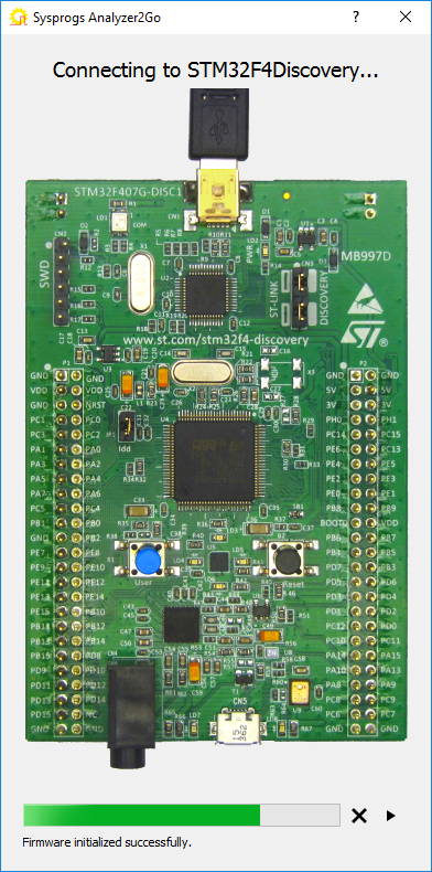
- When the board is ready to be used as a logic analyzer, Analyzer2Go will display the picture of the board and the pins that can be used to capture signals:
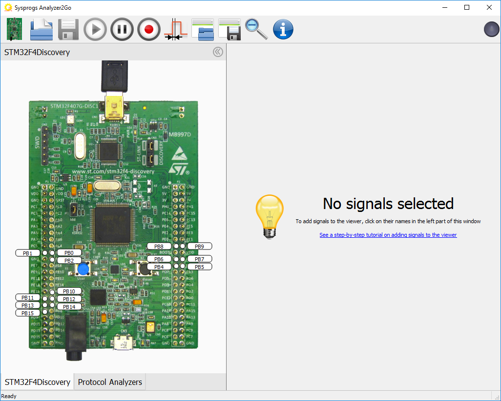
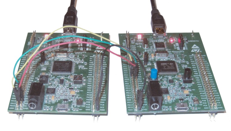
- Connect the ground line on the 2 boards. Then connect the pins generating the output signals on the first board to the input pins on the second board:
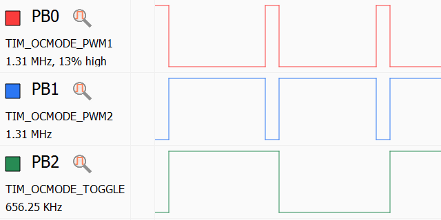
- Click on the input pins to begin sampling the signal on them. Analyzer2Go will immediately begin showing the signal level there:
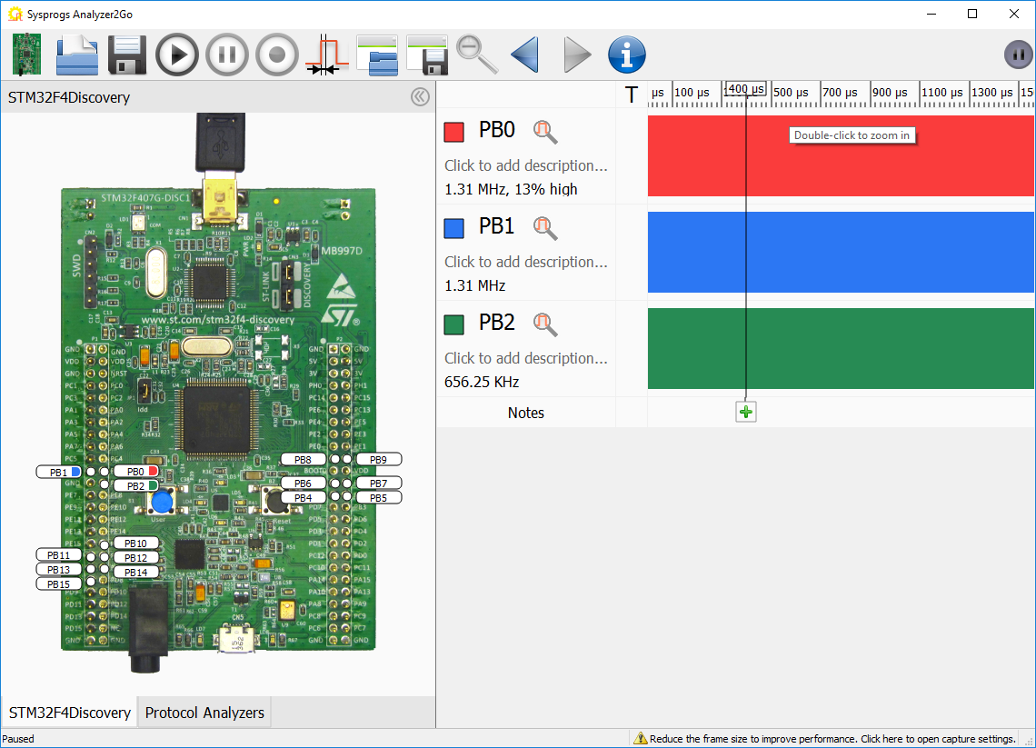
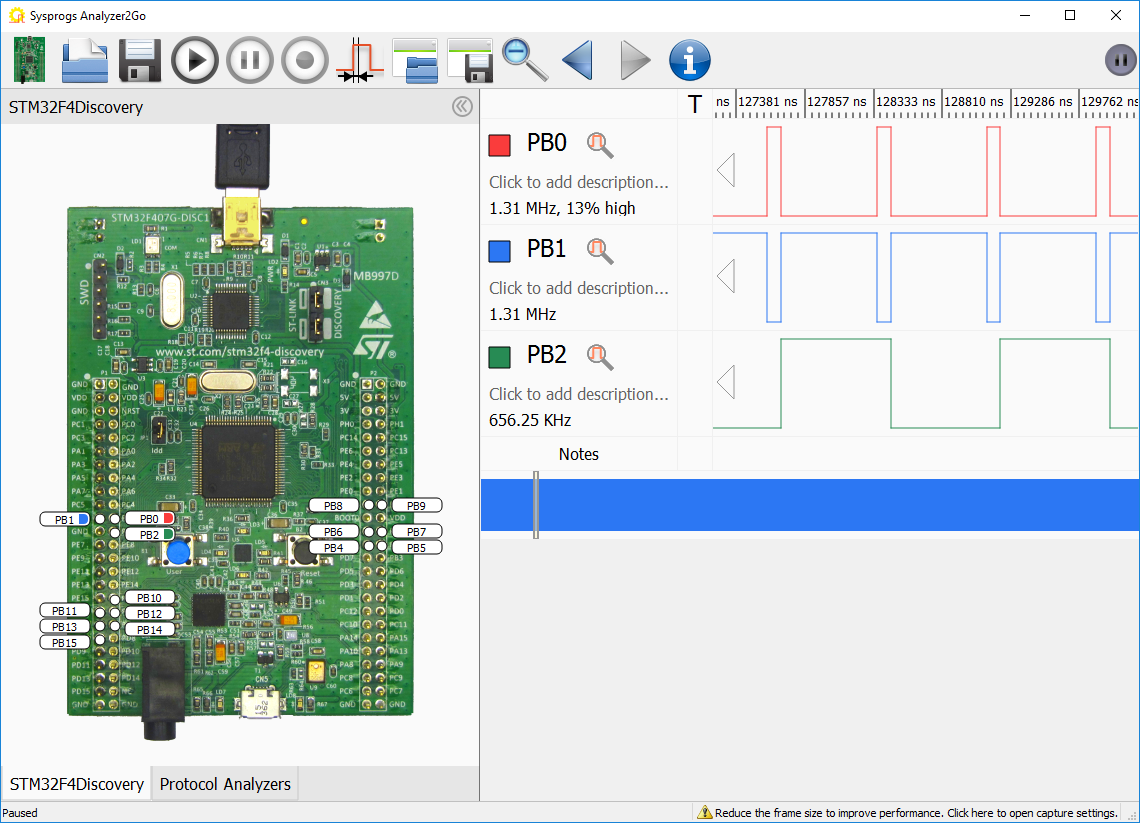
- If the signal switches too fast to be meaningfully displayed on the screen, Analyzer2Go can automatically zoom to a meaningful scale if you double-click on it:
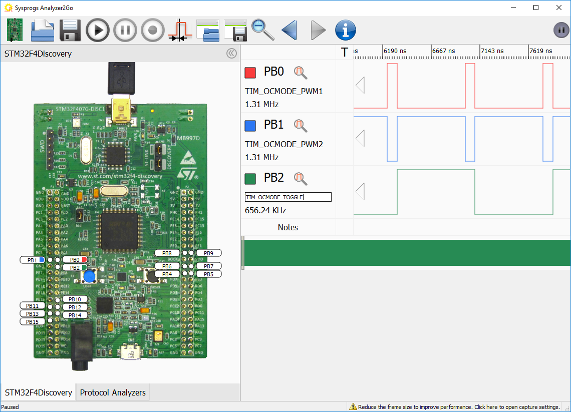
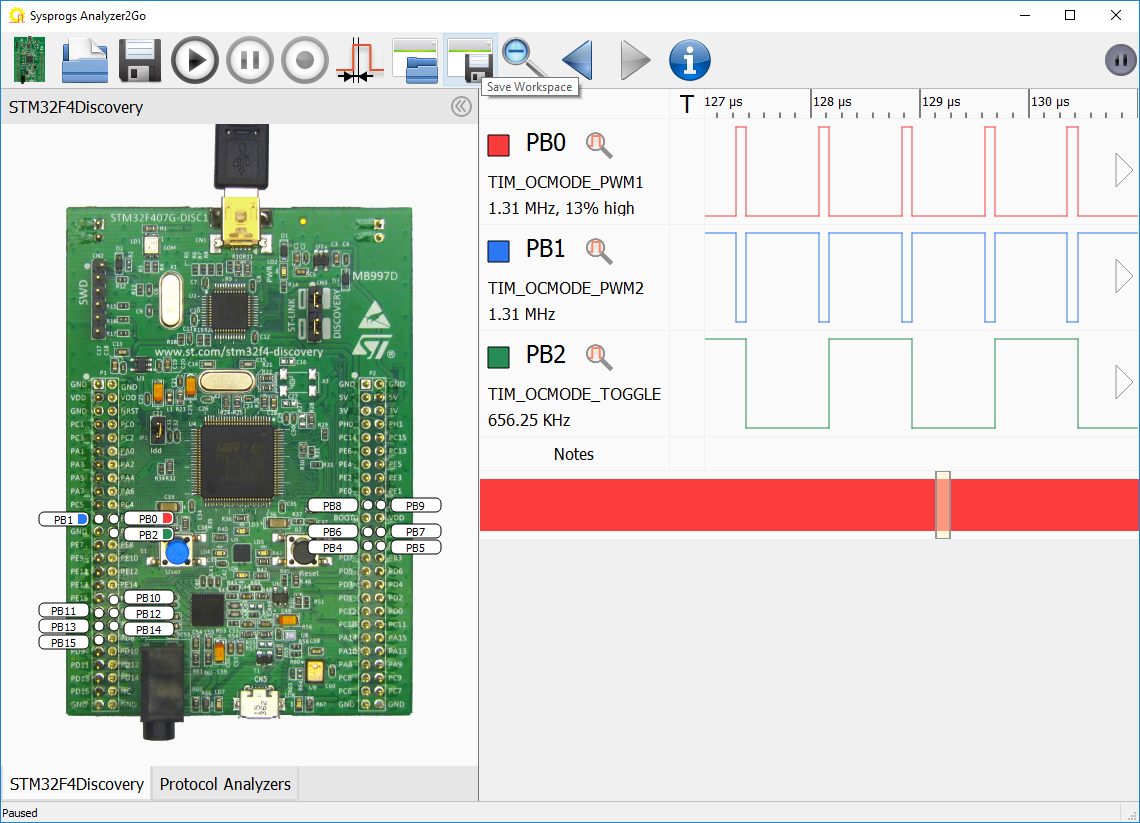
- You can add meaningful descriptions to the signals to simplify distinguishing them. They will be preserved next time you start Analyzer2Go with the same board:
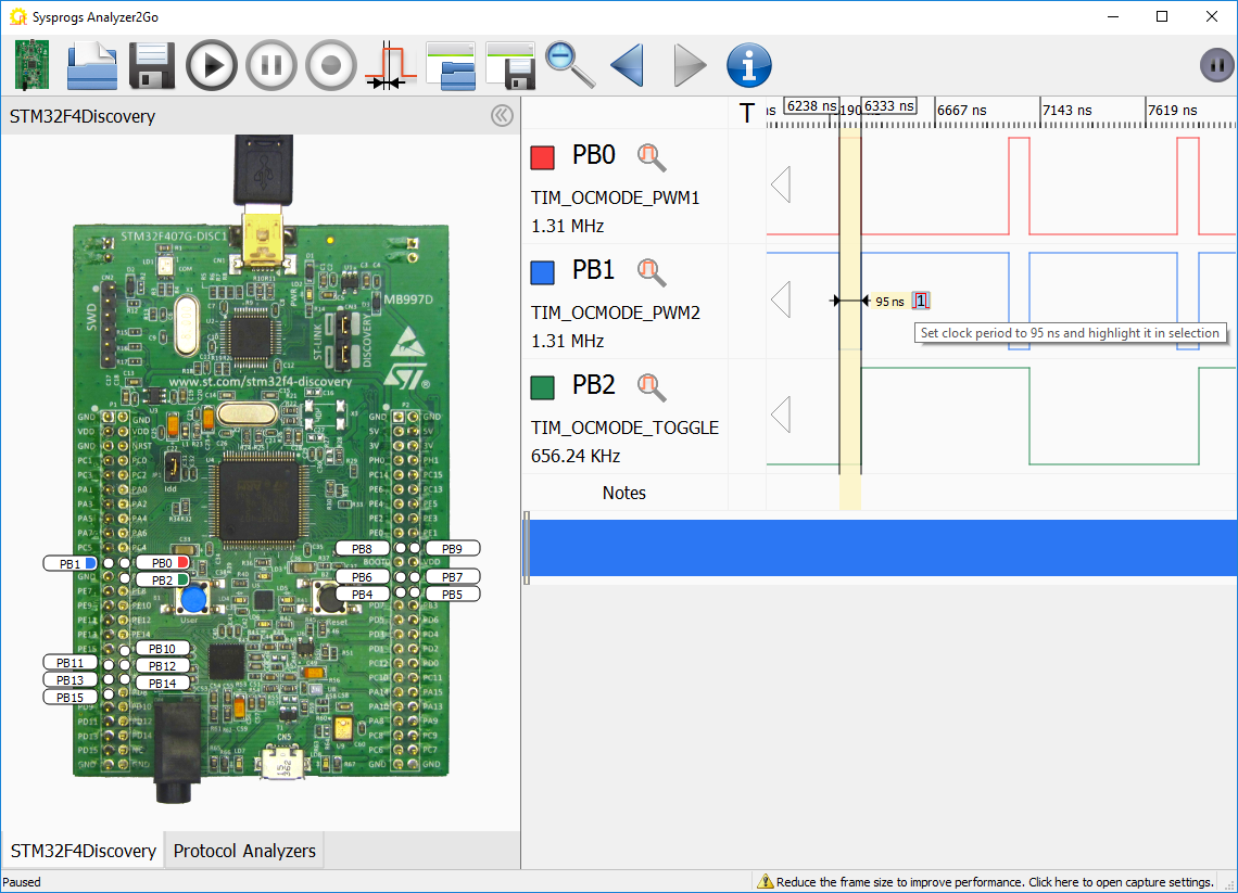
- Select one of the short pulses to measure its length. Then click on the “1” icon to set the selected time span as a reference clock period:
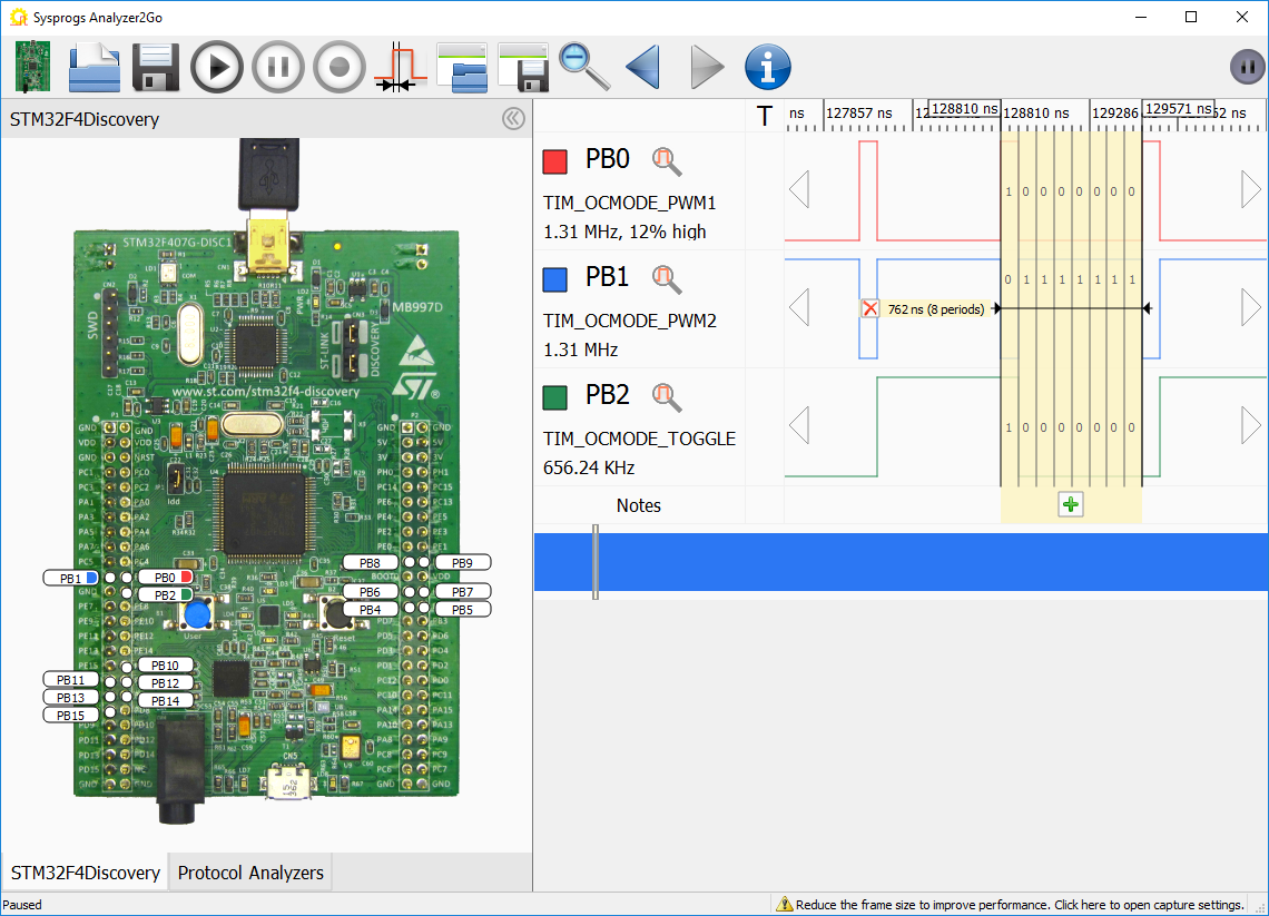
- If you now select the entire clock period, Analyzer2Go will automatically show how many reference clocks fit in the selection and will the values of all signals in each period:
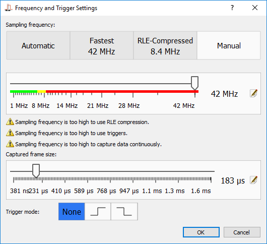
- If you are analyzing signals with short period, you can significantly increase the FPS by reducing the amount of data captured in a single frame. Click the “sampling frequency and triggers” button and reduce the sampling buffer size to ~1/5 of the maximum value:
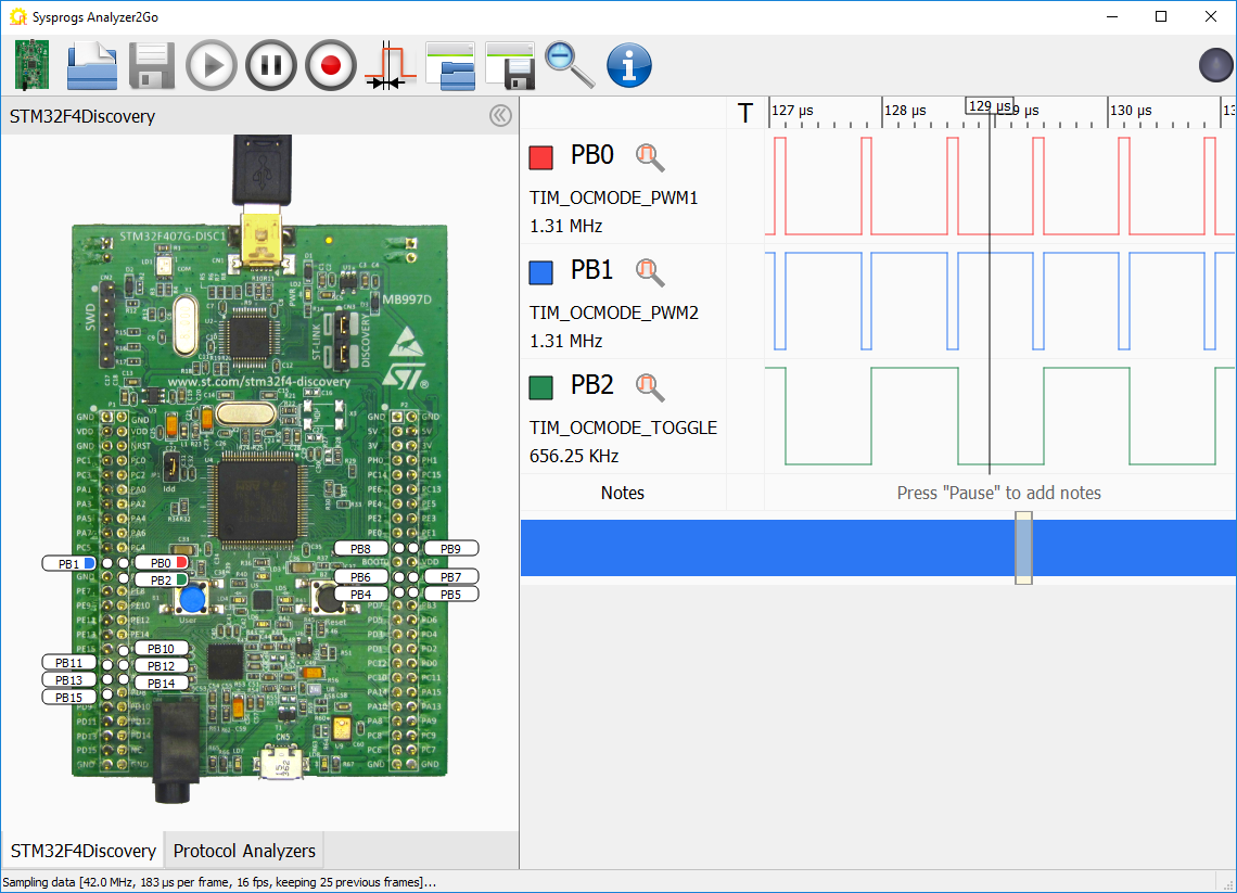
- The amount of frames captured per second will now greatly increase. Check the status bar below to see the sampling parameters:
- Next time you start Analyzer2Go with the same board, it will remember the selected signals, their names and the sampling parameters. You can also save them to workspace files and load them later using the “Save Workspace” button:
Starting from version 2.0 Analyzer2Go is compatible with the Cypress SuperSpeed Explorer Kit, supporting continuous capture at 200MHz via the fast USB 3.0 interface. Check out the SuperSpeed tutorial for details.