Creating a Basic LED Driver for Raspberry Pi
This tutorial demonstrates how to develop and debug a basic hardware driver for Raspberry PI. It will demonstrate the following techniques:
- Controlling the BCM2708/BCM2835 peripherals by accessing their hardware registers
- Creating a sysfs device object to provide user-mode control interface
- Using software timers provided by Linux Kernel
We will create a kernel module that will make an LED connected to the Raspberry Pi blink with a specified period. The user-mode applications will be able to modify the period via a sysfs interface. Note that the Raspberry Pi kernel already comes with a GPIO driver that allows user-mode applications to control the GPIO pins (and LEDs connected to them) directly, however we will not reuse it and will build our driver from scratch to demonstrate direct hardware access.
- First of all, create a basic kernel module project for Raspberry Pi by following this tutorial. Ensure that you can build and debug your module.
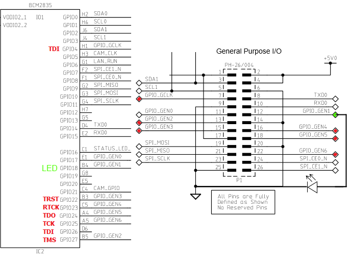
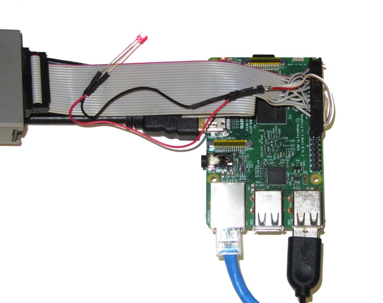
- Connect an LED to one of the GPIO pins not involved in JTAG debugging. In this example we will use the GPIO_GEN1 signal that corresponds to pin 12 on P1 and GPIO18:
- According to the BCM2835 peripheral description, the GPIO pins can be controlled by first configuring them as output by writing to one of GPFSELx registers and then writing to GPFSETx/GPFCLRx registers. We will define a structure describing the GPIO registers and provide functions for controlling GPIO pins using it:
struct GpioRegisters { uint32_t GPFSEL[6]; uint32_t Reserved1; uint32_t GPSET[2]; uint32_t Reserved2; uint32_t GPCLR[2]; }; struct GpioRegisters *s_pGpioRegisters; static void SetGPIOFunction(int GPIO, int functionCode) { int registerIndex = GPIO / 10; int bit = (GPIO % 10) * 3; unsigned oldValue = s_pGpioRegisters-> GPFSEL[registerIndex]; unsigned mask = 0b111 << bit; printk("Changing function of GPIO%d from %x to %x\n", GPIO, (oldValue >> bit) & 0b111, functionCode); s_pGpioRegisters-> GPFSEL[registerIndex] = (oldValue & ~mask) | ((functionCode << bit) & mask); } static void SetGPIOOutputValue(int GPIO, bool outputValue) { if (outputValue) s_pGpioRegisters->GPSET[GPIO / 32] = (1 << (GPIO % 32)); else s_pGpioRegisters->GPCLR[GPIO / 32] = (1 << (GPIO % 32)); } - Now we need to set s_pGpioRegisters to the address of the GPIO registers in memory. Include the <asm/io.h> and <mach/platform.h> files and add the following line to your init() function:
s_pGpioRegisters = (struct GpioRegisters *)__io_address(GPIO_BASE);
The GPIO_BASE is the base address of the GPIO registers defined in platform.h.
- Now we will make the LED blink with a given period (1 second in this example). If we were writing a user-mode application, we could just make an infinite loop with a call to sleep() inside it. However if we do that in our init() function, we will lock up the kernel and prevent other modules from being loaded until init() returns. Thankfully, the kernel provides an easy mechanism to work around this – timers. All we need to do is create a timer and set it to fire one second from ‘now’. Once it fires, we toggle the state of our LED and set it to fire in a second again. The timer will consist of a timer object and a timer callback that will be invoked every second:
struct GpioRegisters { uint32_t GPFSEL[6]; uint32_t Reserved1; uint32_t GPSET[2]; uint32_t Reserved2; uint32_t GPCLR[2]; }; struct GpioRegisters *s_pGpioRegisters; static void SetGPIOFunction(int GPIO, int functionCode) { int registerIndex = GPIO / 10; int bit = (GPIO % 10) * 3; unsigned oldValue = s_pGpioRegisters-> GPFSEL[registerIndex]; unsigned mask = 0b111 << bit; printk("Changing function of GPIO%d from %x to %x\n", GPIO, (oldValue >> bit) & 0b111, functionCode); s_pGpioRegisters-> GPFSEL[registerIndex] = (oldValue & ~mask) | ((functionCode << bit) & mask); } static void SetGPIOOutputValue(int GPIO, bool outputValue) { if (outputValue) s_pGpioRegisters-> GPSET[GPIO / 32] = (1 << (GPIO % 32)); else s_pGpioRegisters-> GPCLR[GPIO / 32] = (1 << (GPIO % 32)); } - Finally we need to add code for setting up the timer in our init() function and code for deleting it in the
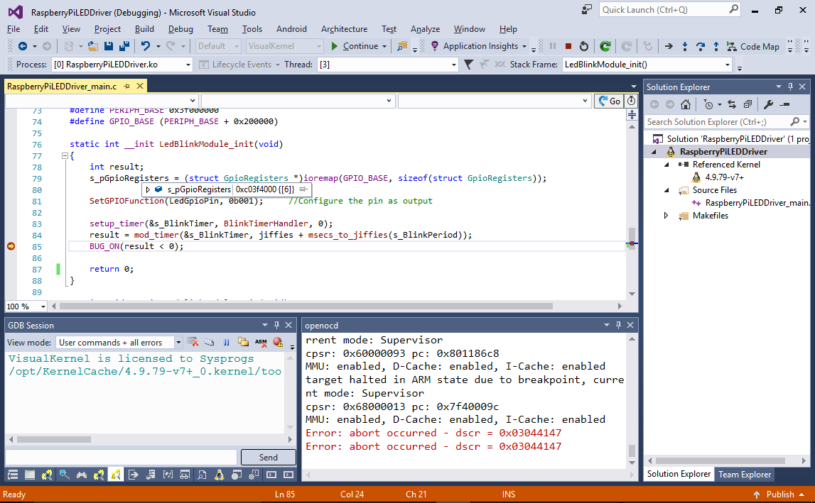
exit() function. We also need to configure the GPIO pin in the output mode before we start toggling it:static int __init LedBlinkModule_init(void) { int result; s_pGpioRegisters = (struct GpioRegisters *)__io_address(GPIO_BASE); SetGPIOFunction( LedGpioPin, 0b001); //Output setup_timer(&s_BlinkTimer, BlinkTimerHandler, 0); result = mod_timer( &s_BlinkTimer, jiffies + msecs_to_jiffies( s_BlinkPeriod)); BUG_ON(result < 0); } static void __exit LedBlinkModule_exit(void) { SetGPIOFunction( LedGpioPin, 0); //Configure the pin as input del_timer(&s_BlinkTimer); } - Build your module and start debugging it. You can step through the initialization function to double-check that all necessary initialization succeeds:
- Once you hit F5 to resume the Raspberry Pi kernel the LED will start blinking:
- Now we will create a sysfs-based user-mode interface for changing the LED blinking frequency. This is accomplished in 3 steps:
- Register a device class (e.g. /sys/class/LedBlink)
- Register a device object within the class (e.g. /sys/class/LedBlink/LedBlink)
- Create a sysfs file for the device object (e.g. /sys/class/LedBlink/LedBlink/period)
First of all we will define a function that will receive a string value, convert it to an integer and update the LED blinking period accordingly:
static ssize_t set_period_callback(struct device* dev, struct device_attribute* attr, const char* buf, size_t count) { long period_value = 0; if (kstrtol(buf, 10, &period_value) < 0) return -EINVAL; if (period_value < 10) //Safety check return -EINVAL; s_BlinkPeriod = period_value; return count; } static DEVICE_ATTR(period, S_IWUSR | S_IWGRP, NULL, set_period_callback); static struct class *s_pDeviceClass; static struct device *s_pDeviceObject; - Create the class, device and file objects from the init() function:
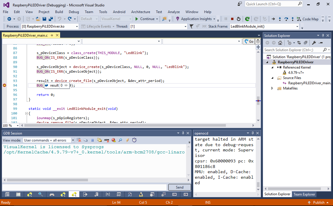
s_pDeviceClass = class_create(THIS_MODULE, "LedBlink");
BUG_ON( IS_ERR( s_pDeviceClass));

s_pDeviceObject = device_create( s_pDeviceClass,
                                NULL,
                                0,
                                NULL,
                                "LedBlink");
BUG_ON( IS_ERR( s_pDeviceObject));

result = device_create_file( s_pDeviceObject, &dev_attr_period);
BUG_ON(result < 0);
- Finally add the cleanup code to the exit() function:
device_remove_file( s_pDeviceObject, &dev_attr_period);
device_destroy( s_pDeviceClass, 0);
class_destroy( s_pDeviceClass);
You will need to switch the license of your module to GPL to be able to call device_destroy().
- Build your module and start debugging it. You can step through the initialization to re-check everything:
- Connect to your Raspberry Pi over SSH and write the new period value to the /sys/class/LedBlink/LedBlink/period file using the root terminal:
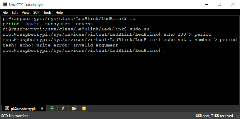
You will see how the LED blinking period will change. Note that if you write a value that is not a number, you will get an error (because set_period_callback() will return -EINVAL).
You can download the source code of the LED driver described in this tutorial here.